High efficiency portable power plant

Inactive Publication Date: 2016-04-21
MCKINLEY SERVICE EQUIP
View PDF10 Cites 4 Cited by
  • Summary
  • Abstract
  • Description
  • Claims
  • Application Information

AI Technical Summary

Benefits of technology

[0008]The present portable power plant gains its high efficiency from the combination of improvements within the art to accomplish the objective of increasing efficiency of the power plant, reducing temperature control issues within the engine making for an improved generator for hot or cold climates and inclement weather, low fuel use to enhance running time and consume smaller fuel amounts, to reduce vibrational forces

Problems solved by technology

However, the prior art inventions do not disclose the same or similar elements as the present high efficiency portab

Method used


Image

  • High efficiency portable power plant
  • High efficiency portable power plant
  • High efficiency portable power plant

Examples


Example

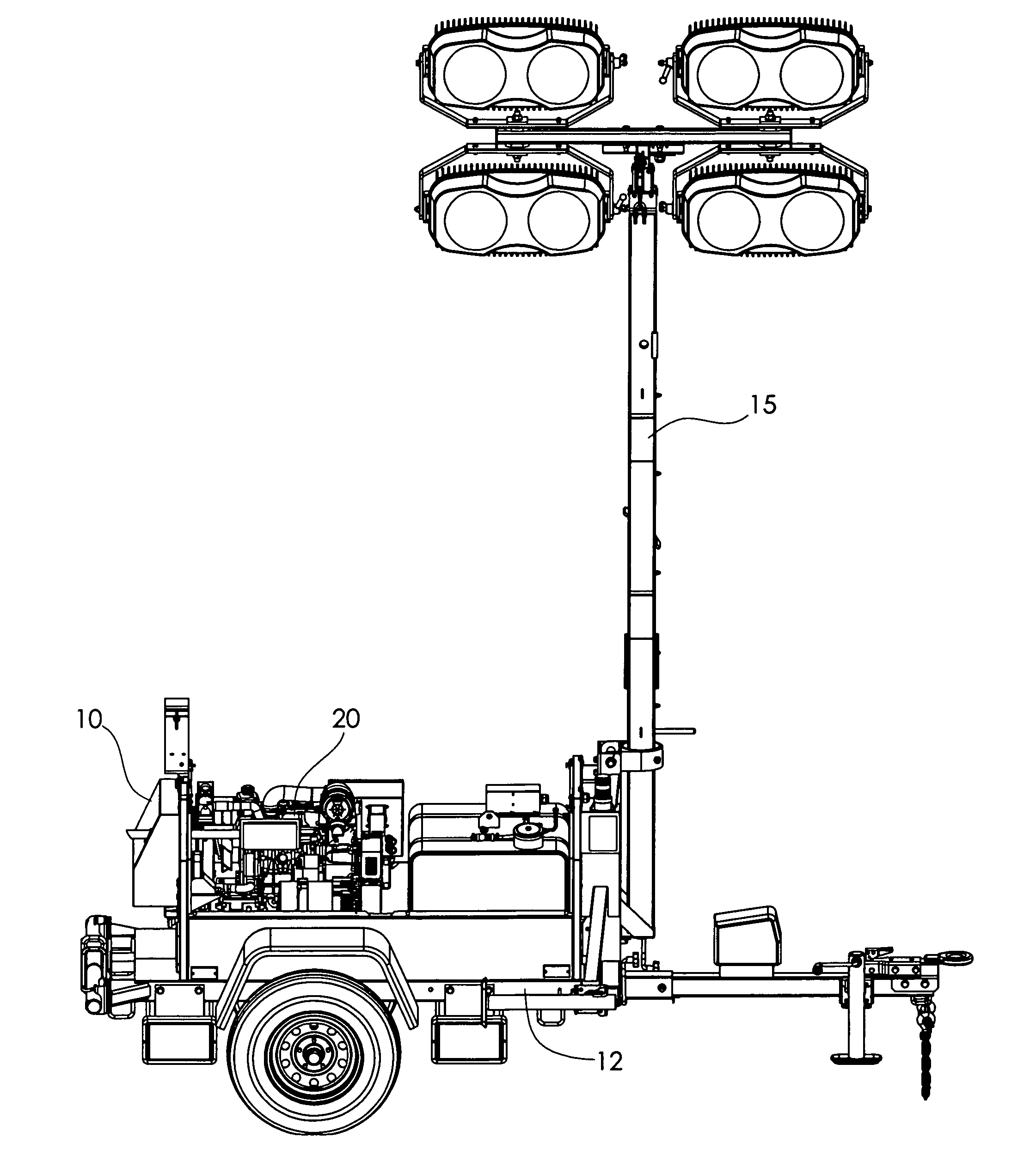
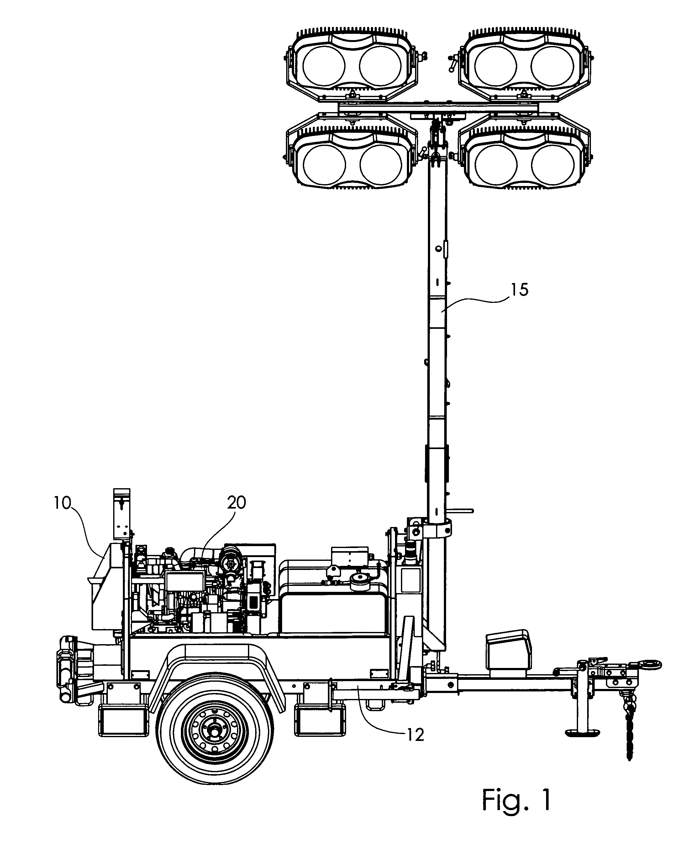
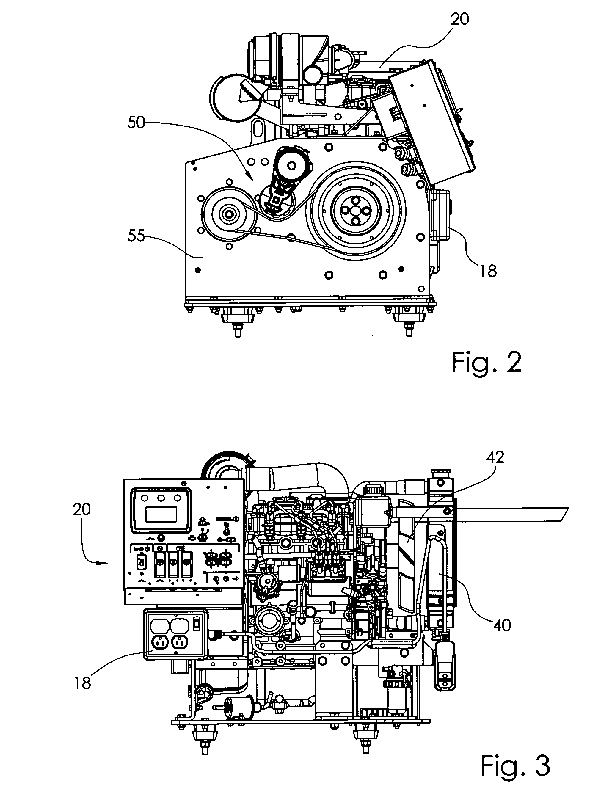
[0024]A portable electrical generating power plant 10 producing electrical power for the operation of electrical equipment, as shown in FIGS. 1-9 of the drawings, provides a portable transport trailer 12 upon which is mounted a high efficiency diesel engine 20 having a compact and light weight profile and having a low noise output, extended servicing intervals and the ability to produce and high power output, operating on a diesel or bio-diesel fuel, a belt drive and pulley system 50 providing a wide belt 90 drive between a large engine pulley 60 and a smaller generator pulley 70 attached to an electrical generator 30, and a coolant system 40 to maintain a constant operational temperature regardless of the environmental temperature within which the power plant 10 is operated, wherein the engine 20 is operated at a lower rpm while maintaining a high rpm on the generator pulley 70, extending the operational time of the engine 20, producing minimal 1600 watts at 60 Hz of electrical sup...


PUM


Abstract

A high efficiency and high output electrical generator sized to match the electrical demands of generating power for lighting and operation of large amperage electrical machinery including an improved gear belt drive designed to allow the a diesel engine to run at a lower rpm, resulting in optimal fuel conservation benefit and longer run time on a tank of fuel, the engine, generator and motor mounts form a uniquely unitized mounting system employing a modular bell housing and generator adaptor plate supporting the engine, gears, belt drive and generator components.

Description

CROSS REFERENCE TO RELATED APPLICATIONS[0001]Applicants claim the benefit of U.S. Provisional Patent Application No. 62 / 122,412, filed by the same inventors on Oct. 20, 2014.I. BACKGROUND OF THE INVENTION[0002]1. Field of Invention[0003]A high efficiency and high output electrical generator sized to match the electrical demands of generating power for lighting and operation of large amperage electrical machinery including an improved gear belt drive designed to allow the a diesel engine to run at a lower rpm, resulting in optimal fuel conservation benefit and longer run time on a tank of fuel, the engine, generator and motor mounts form a uniquely unitized mounting system employing a modular bell housing and generator adaptor plate supporting the engine, gears, belt drive and generator components.[0004]2. Description of Prior Art[0005]A preliminary review of prior art patents was conducted by the applicant which reveal prior art patents in a similar field or having similar use. Howe...

Claims


Application Information

Patent Timeline
IPC IPC(8): F02B63/04H02K7/18H02K9/04H02K7/00
CPCF02B63/047H02K9/04H02K7/1815H02K7/003F21S2/005F21S8/085F21V14/02F21V21/22F21V21/30F21W2131/403F21Y2115/10H02K7/1004
Inventor FERGUSON, KEVIN L.MCKINLEY, STEVEN C.HILBISH, KEITHWARNER, JON
Owner MCKINLEY SERVICE EQUIP
Why Eureka
Try Eureka