

A light emitting arrangement for Anti-fouling of a protected surface
- Summary
- Abstract
- Description
- Claims
- Application Information
AI Technical Summary
Benefits of technology
Problems solved by technology
Method used
Image

Examples
first embodiment
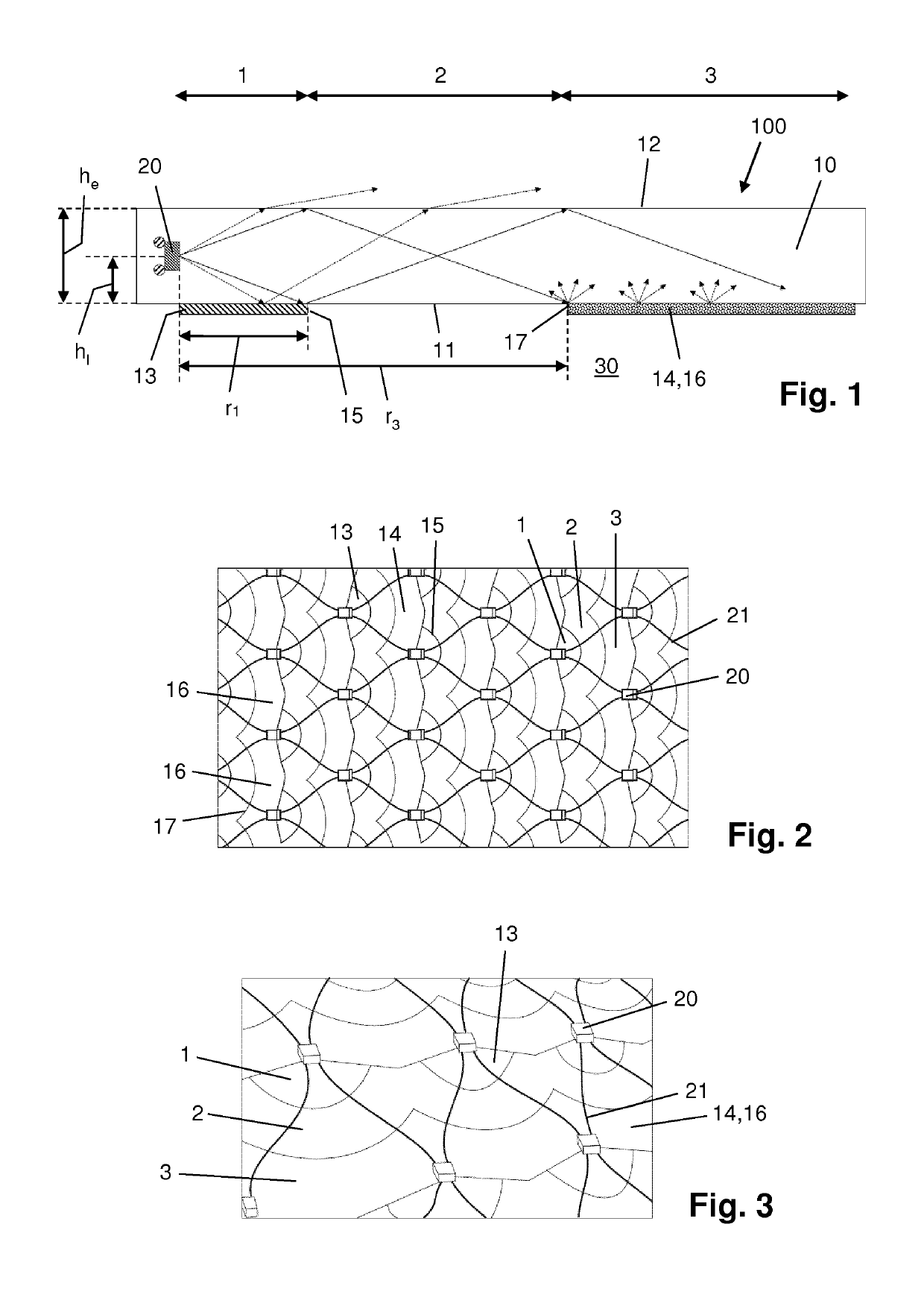
[0031]FIGS. 1-3 relate to a light emitting arrangement 100 according to the invention. The light emitting arrangement 100 comprises an optical medium in the form of a slab 10 of ultraviolet transparent silicone, and furthermore comprises a plurality of light sources in the form of side-emitting ultraviolet LEDs 20 embedded in the slab 10. In FIGS. 2 and 3, it can be seen that in the shown example, the light sources 20 are arranged in a series of parallel connections in a grid 21, particularly a grid 21 having a chicken-wire structure. That does not alter the fact that other arrangements of the light sources 20 are feasible within the framework of the invention.
[0032]The slab 10 has a back surface 11 for facing a protected surface 30, i.e. a surface which needs to be kept clean from bio fouling in an environment in which the surface is exposed to a fouling liquid, at least during a part of the lifetime thereof, and an emission surface 12 for emitting the ultraviolet light emitted by ...
second embodiment
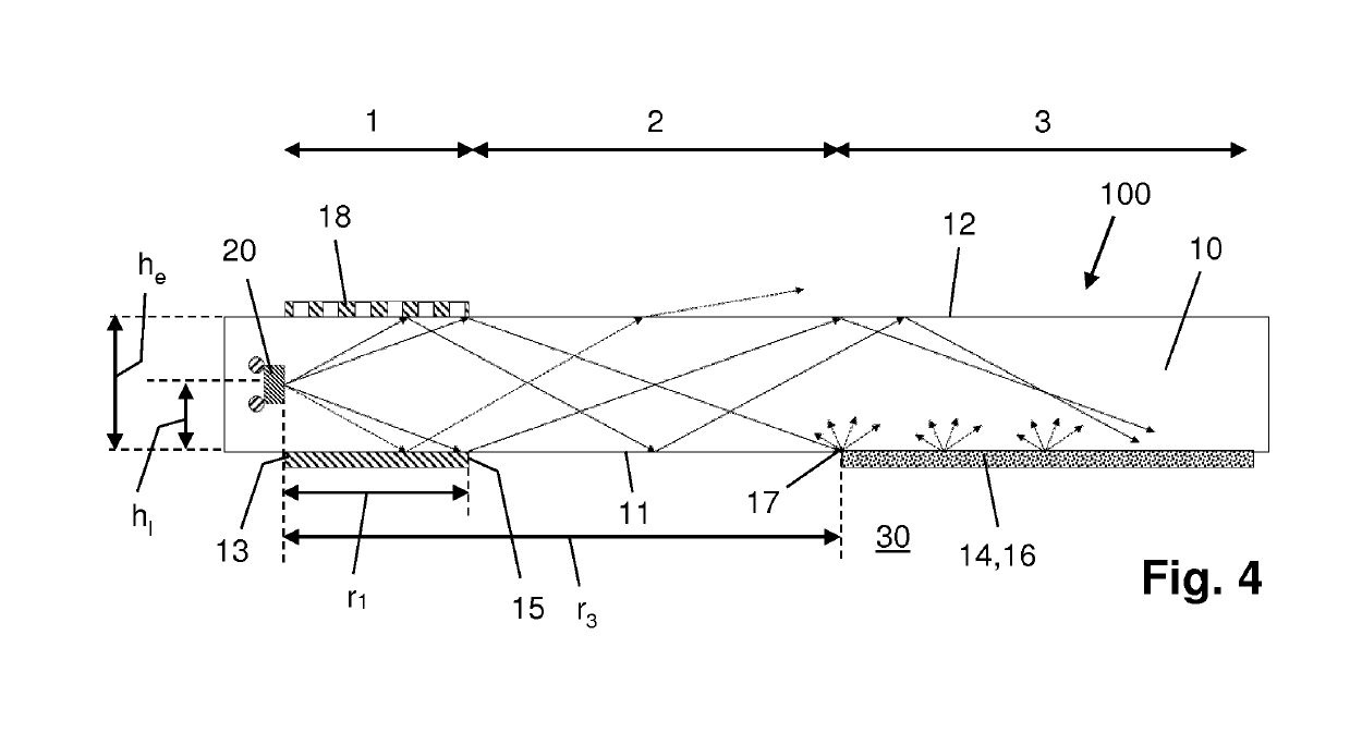
[0041]FIG. 4 relates to a light emitting arrangement 100 according to the invention, and particularly illustrates a possibility of applying an additional mirror 18 in the first zone 1, namely a mirror 18 for at least partially covering the emission surface 12 of the slab 10 in the first zone 1, a reflective side of the mirror 18 facing the emission surface 12. It is practical for such an additional mirror 18 to be semi-transparent to the light emitted by the LED 20. In view thereof, the mirror 18 may be a patterned mirror as diagrammatically indicated in FIG. 4. By having the additional mirror 18, it is possible to ensure that even more light is made to propagate from the first zone 1 towards the second zone 2 and the third zone 3 and to have a distribution of the light across the emission surface 12 of the slab 10 which is optimized even further. In that respect, it is an advantageous possibility for the additional mirror 18 to be designed in such a way that the semi-transparency t...
PUM
 Abstract
Description
Claims
Application Information