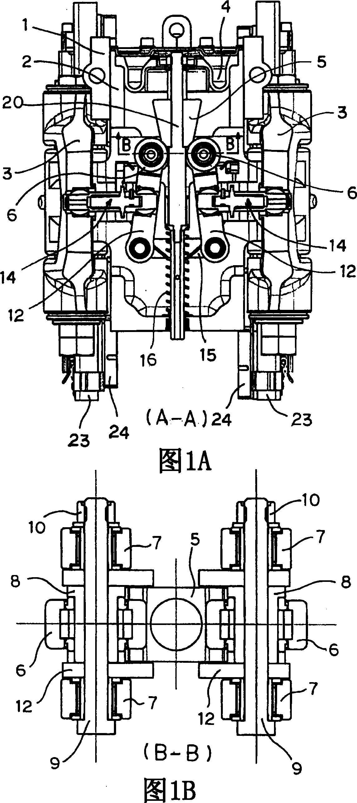
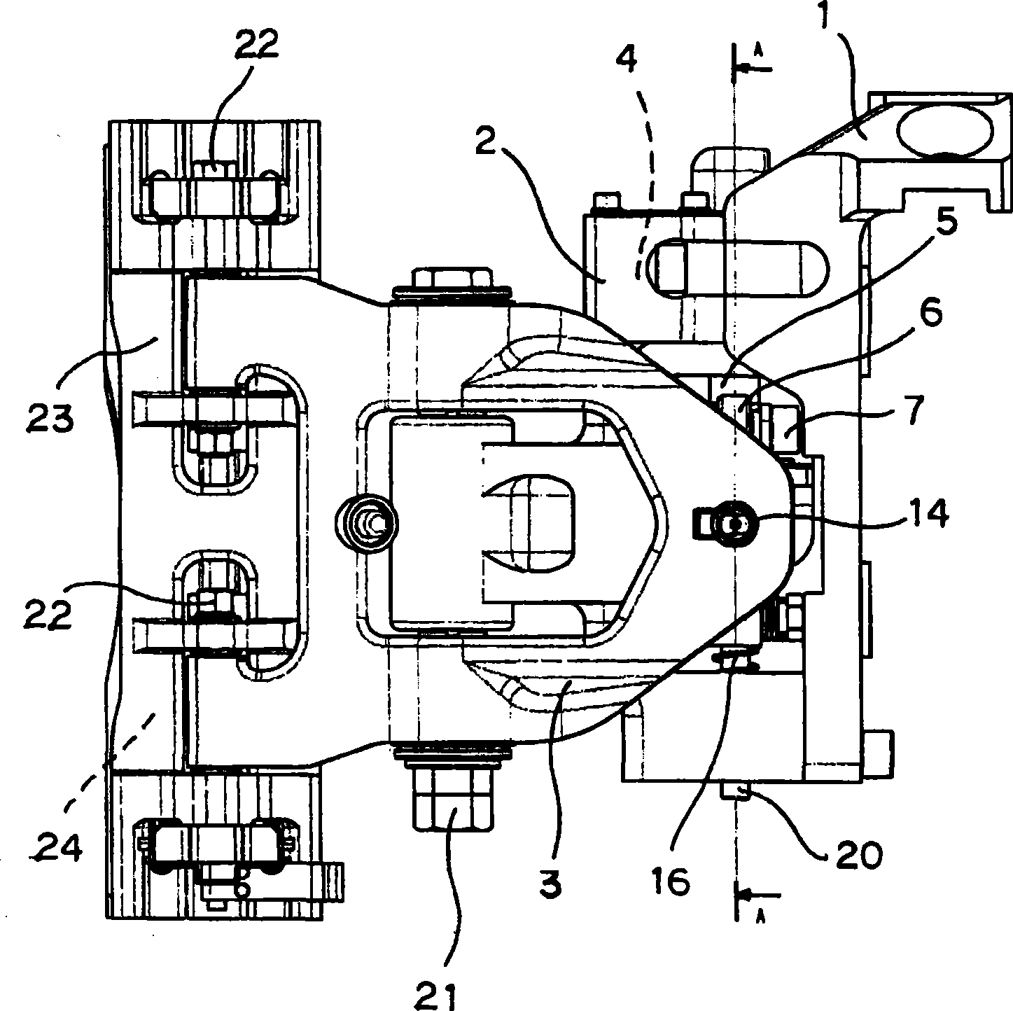
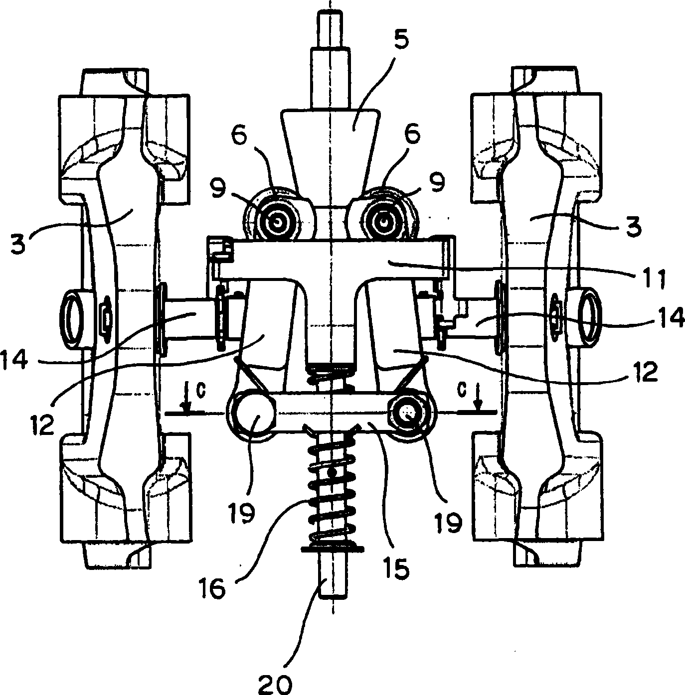
Pressing and actuating mechanism of disc brake device
A disc brake and brake arm technology, applied in the direction of brake actuator, brake type, axial brake, etc., can solve the problem of increasing the swing angle of the brake arm, and achieve less sliding resistance, less sliding, The effect of increasing the multiplier efficiency
- Summary
- Abstract
- Description
- Claims
- Application Information
AI Technical Summary
Problems solved by technology
Method used
Image
Examples
no. 2 example
[0071] 9(A) to 9(B) show a brake device according to a second embodiment of the present invention having a spacer bracket with an adjustment function. FIG. 9(A) is a sectional view of the whole brake device in which the adjustment and correction mechanism is disposed on the brake arm side, and FIG. 9(B) is a sectional view of the main part of the brake device.
[0072] As shown in Fig. 9(A) ~ Fig. 9(B), the upper ends 302A, 302A of a pair of brake arms 302, 302 are expanded and pressed, and the pad brackets 301, 301 installed on the lower part of the shaft are fixed The moving blocks 308, 308 perform a pressing action. In the above-mentioned disc brake device, when the brake blocks 308, 308 mounted on the pad brackets 301, 301 are worn and overstroke occurs, regardless of the above-mentioned brake arms 302, Regardless of the posture of 302 , adjustment and correction mechanisms 310 , 310 for maintaining brake pads 308 , 308 and disk rotor R in parallel are provided between bra...
no. 3 example
[0079] 10(A) to 10(C) show a disc brake device according to a third embodiment of the present invention in which the adjustment and correction mechanism is disposed on the side of the pad holder. Fig. 10(A) is a sectional view of the whole brake device, and Fig. 10(B) is a sectional view of main parts of the brake device. In this embodiment, as shown in FIG. 10(B), which is an enlarged view of the lower part of the arm shaft 304 of the brake arm 302 in FIG. 10(A), as shown in FIG. Between the block holders 301 , unlike the device of the second embodiment described above, the configuration inside the block holder 301 is provided above the shaft support portion 305 of the block holder 301 . In addition, a return spring 316 that biases the friction lever 306 that is a part of the adjustment correction mechanism 310 is arranged on the brake arm 302 side.
[0080] As shown in FIG. 10(C), the receiving hole 302C of the brake arm 302 accommodates one end of the friction rod 306 havi...
no. 4 example
[0083] 11(A) to 11(B) show a brake device according to a fourth embodiment of the present invention including a pad holder with an adjustment function. Fig. 11(A) is an overall sectional view of the brake device provided with a link member, and Fig. 11(B) is an operation diagram of main parts of the brake device. In the braking device of the fourth embodiment, as shown in Fig. 11(A) and Fig. 11(B), the adjustment and correction mechanism is provided with a supporting shaft 307A on the upper part of the housing 303 and a supporting shaft on the upper part of the pad brackets 301, 301. The shaft 307B connects the link members 307, 307. With such a configuration, as shown in the operation diagram of FIG. 11(B), the support shafts 307A, 307B, the spacer shaft 305, and the arm shaft 304 are connected in a parallelogram shape. Therefore, the pad holder 301 appropriately follows the movement of the brake arm 302 that excessively swings as shown by the black arrow during the wear of ...
PUM
 Abstract
Description
Claims
Application Information
 - R&D
- Intellectual Property
- Life Sciences
- Materials
- Tech Scout
- Unparalleled Data Quality
- Higher Quality Content
- 60% Fewer Hallucinations
Browse by: Latest US Patents, China's latest patents, Technical Efficacy Thesaurus, Application Domain, Technology Topic, Popular Technical Reports.
© 2025 PatSnap. All rights reserved.Legal|Privacy policy|Modern Slavery Act Transparency Statement|Sitemap|About US| Contact US: help@patsnap.com


