Bearing bush and composite motion device using this bearing bush

一种轴承衬套、复合运动的技术,应用在轴承部件的刚性支架、轴承、机电装置等方向,能够解决不提高滑动阻力、花费工时等问题,达到提高精度、廉价制造的效果

Inactive Publication Date: 2007-04-11
THK CO LTD
View PDF1 Cites 10 Cited by
  • Summary
  • Abstract
  • Description
  • Claims
  • Application Information

AI Technical Summary

Problems solved by technology

[0011] However, in order to completely eliminate the gap between the bearing bush and the shaft member without increasing the sliding resistance, it is still necessary to strictly control the dimensions of the inner diameter of the bearing bush and the outer diameter of the shaft member, and there is a problem that it takes man-hours for production.

Method used


Image

  • Bearing bush and composite motion device using this bearing bush
  • Bearing bush and composite motion device using this bearing bush
  • Bearing bush and composite motion device using this bearing bush

Examples


Embodiment Construction

[0030] Next, the bearing bush of the present invention will be described in detail with reference to the accompanying drawings.

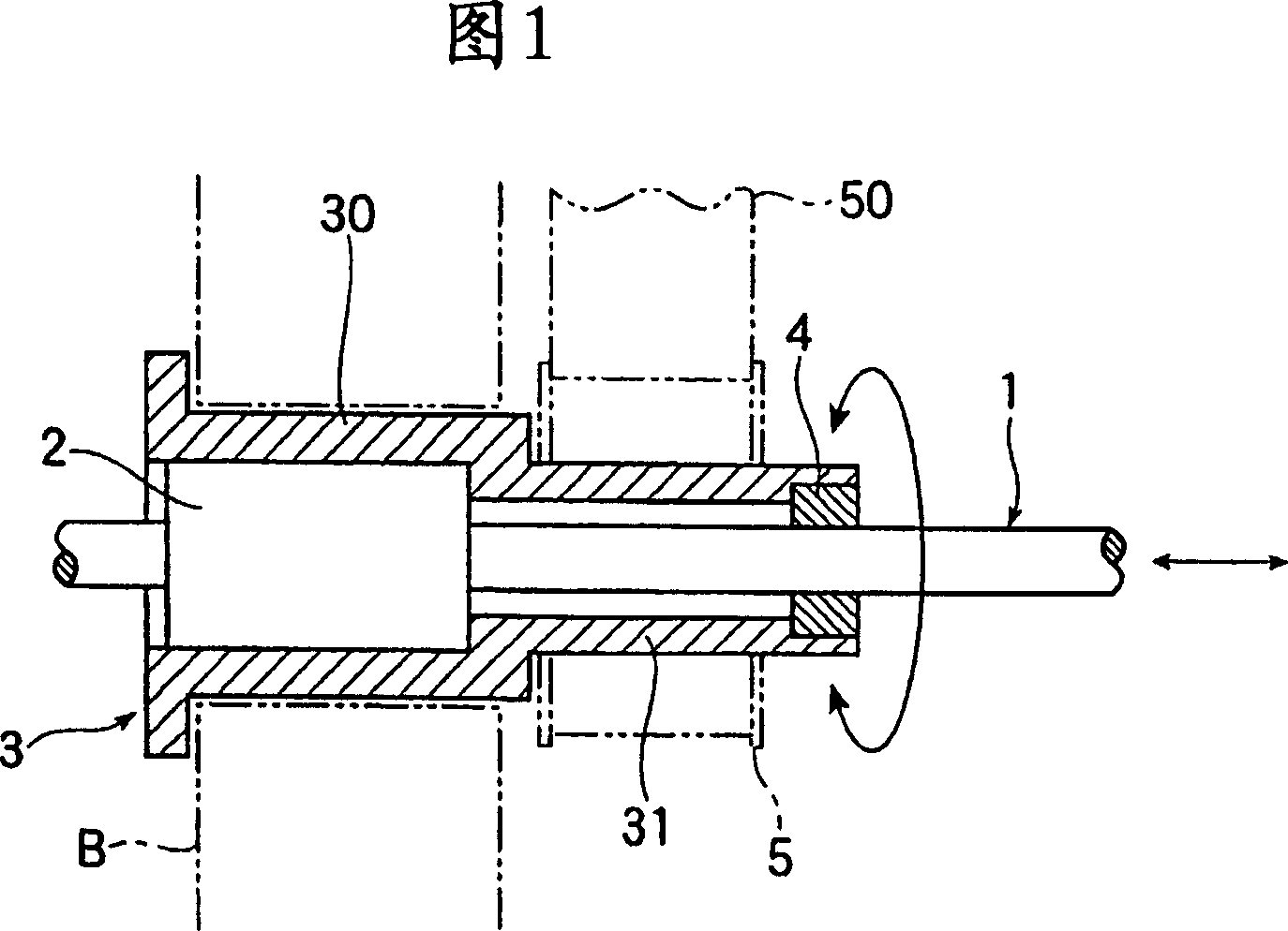
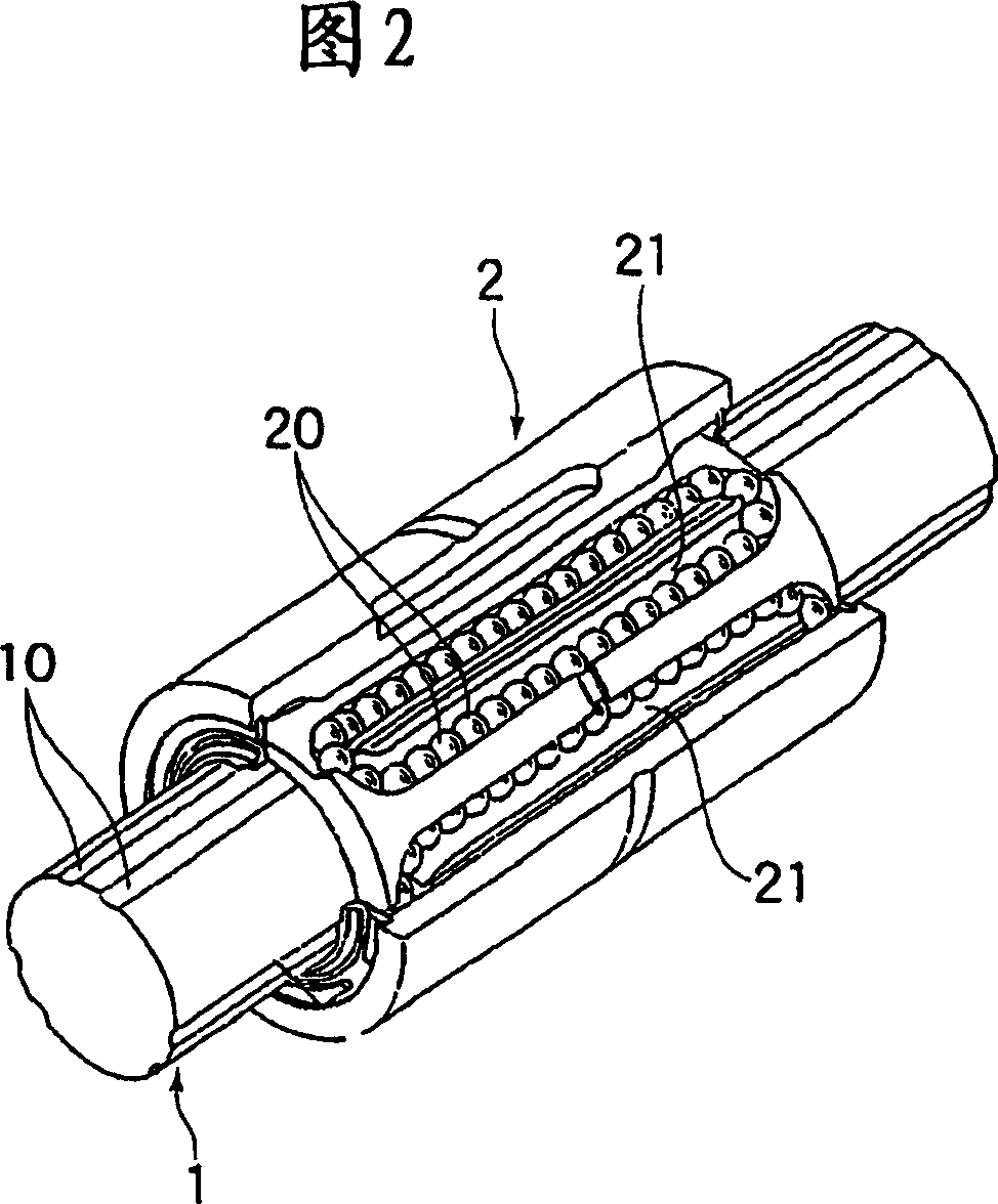
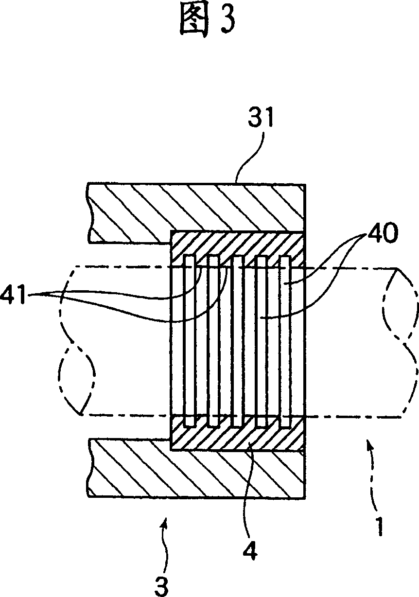
[0031] FIG. 1 is a diagram showing an example of a compound kinematic device that supports the forward and backward motion of a spline shaft using a bearing bush according to the present invention. This device is used as a main shaft of a tool changing device, etc., and consists of a spline shaft 1 used as the main shaft, a spline nut 2 that can freely reciprocate in the axial direction of the spline shaft 1, and a spline nut 2 that holds the spline nut 2. At the same time, the housing 3 rotatably supported relative to the fixed part B and the bearing bush 4 provided at one end of the housing 3 and guiding the advance and retreat of the spline shaft 1 relative to the housing 3 constitute.

[0032] The spline shaft 1 is provided with an axial forward and backward movement by a ball screw device not shown, a hydraulic cylinder, a pneumatic cylinder, e...


PUM


Abstract

A bearing bush enabling the excellent advancing and retarding motions of a shaft member by eliminating a clearance between the bearing bush and the shaft member to exclude rattling therebetween, capable of reducing a load on dimensional control for both the bearing bush and the shaft member, and manufacturable at low cost and a compound movement device using the bearing bush. The bearing bush (4) pivotally supporting the reciprocating motion of the shaft member (1) in the axial direction comprises an accepting hole through which the shaft member (1) is inserted. Grooves (40) are repeatedly formed, at specified intervals, in the inner peripheral surface of the bearing bush which faces the accepting hole. The inner diameter of the accepting hole is formed equal to or smaller than the outer diameter of the shaft member (1) to press-fit the bearing bush to the outer peripheral surface of the shaft member (1) by so-called a shrink fitted state.

Description

technical field [0001] The present invention relates to a bearing bush that supports the axial forward and backward movement of a shaft member such as a spline shaft. A bearing bush that supports the forward and backward movement of the spline shaft in a compound kinematic device in which the shaft rotates. Background technique [0002] As the spindle of the automatic feeding device of the workpiece or the automatic changing device of the tool in the NC machine tool, it must be able to move forward and backward freely in the axial direction, and can perform rotational movement with high precision, as a support for the movement of the spindle in the axial direction, and relative to the The part that transmits the rotational torque of the main shaft uses a combination of a spline shaft and a spline nut. [0003] In particular, when a spline nut is assembled to a ball spline on a spline shaft with a plurality of balls interposed, and the balls are pressurized, rotational torqu...

Claims


Application Information

Patent Timeline
Patent Type & Authority Applications(China)
IPC IPC(8): F16C31/02F16C29/02F16C29/06F16C31/06F16C33/10F16C33/20F16C35/02F16C23/04H02K41/02H02K41/03
CPCF16C31/02F16C33/20F16C33/10F16C29/02
Inventor 道冈英一饭田胜也松本隆石坂正幸
Owner THK CO LTD
Why Eureka
Try Eureka