Seal structure and control valve using the same

A sealing structure and control valve technology, which is applied in shaft seals, engine seals, valve lifts, etc., can solve the problems of reduced sealing ability and responsiveness, and achieve the effect of reducing sliding resistance

Inactive Publication Date: 2008-04-23
EAGLE INDS
View PDF1 Cites 10 Cited by
  • Summary
  • Abstract
  • Description
  • Claims
  • Application Information

AI Technical Summary

Problems solved by technology

Therefore, the magnitude of the current applied to the solenoid part is not proportional to the operating speed of the spool 106, and the response of the solenoid valve 130 to control the volume of the fluid may deteriorate.
In addition, because the inner peripheral sealing surface of the O-ring 125 is worn due to pressure contact, the sealing ability is reduced.

Method used


Image

  • Seal structure and control valve using the same
  • Seal structure and control valve using the same
  • Seal structure and control valve using the same

Examples


Embodiment Construction

[0021] Next, the sealing structure and control valve according to the embodiment of the present invention will be described in detail with reference to the drawings. The drawings described below are correct drawings based on design drawings.

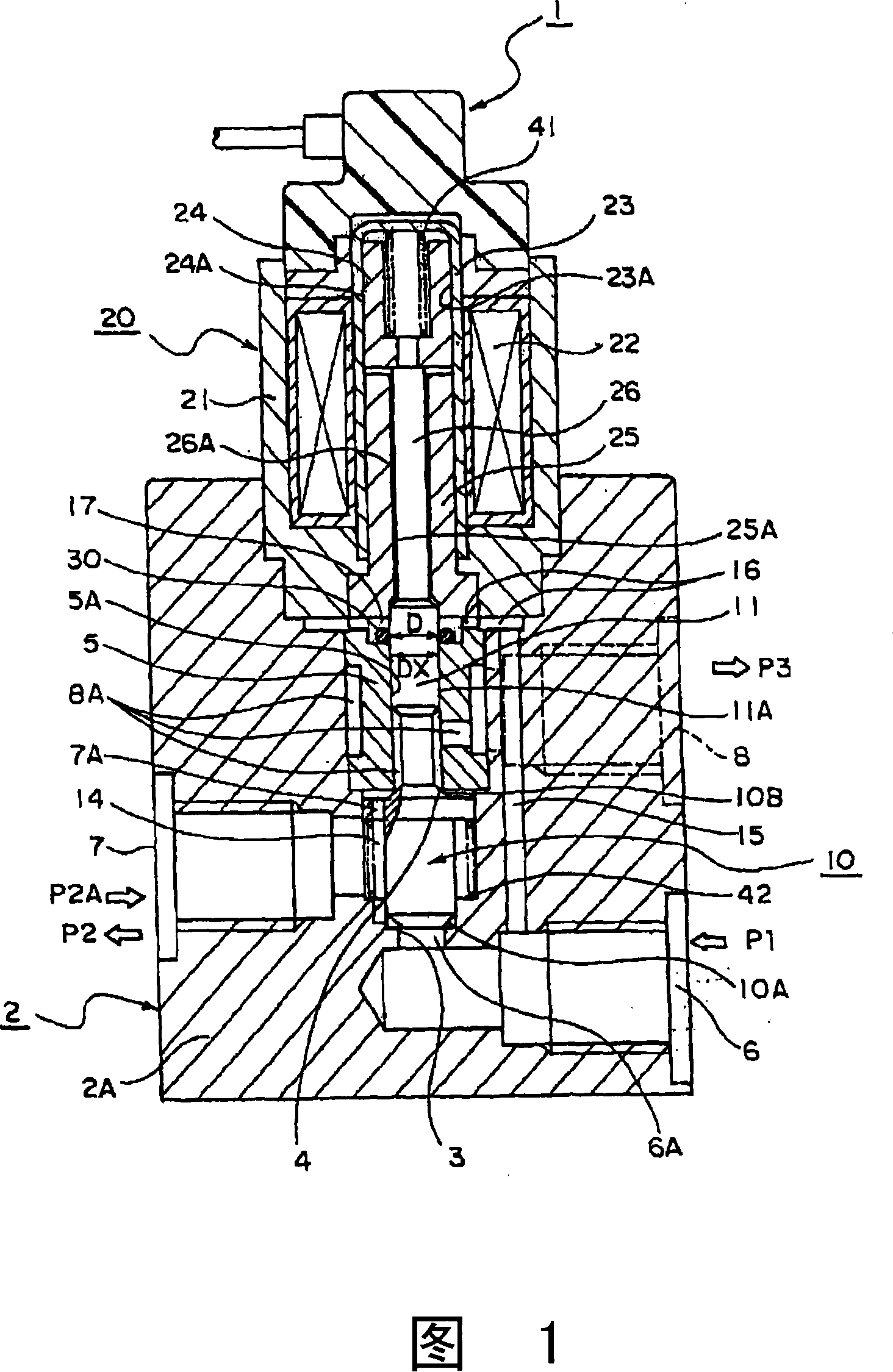
[0022] Fig. 1 is a sectional view showing a control valve according to an embodiment of the present invention. In Fig. 1, 1 is a control valve. This control valve 1 is formed by combining a valve unit 2 and a solenoid unit 20 . A valve housing (also referred to as a valve body) 2A forming an outer diameter of the valve portion 2 is provided on the control valve 1 . A valve chamber 14 is provided on the axis of the valve housing 2A. A first fluid passage 6 through which a first operating fluid (also referred to as operating fluid) P1 flows into the valve chamber 14 from the outside is provided centering on the valve chamber 14 . A first communication passage 6A is formed between the first fluid passage 6 and the valve chamber 14 . Th...


PUM


Abstract

A seal structure sealing a fitted part between the guide surface of a bearing part and a shaft part to prevent a fluid from flowing in a direction from a high-pressure fluid side to a low-pressure fluid side. The seal structure comprises a seal ring storage part having a radial contact surface surrounding the shaft part which is formed on the high-pressure fluid side of the bearing part and a seal ring disposed in the seal ring storage part, allowing its side surface facing the contact surface to come into contact with the contact surface, and allowing its inner peripheral surface to be fitted to the outer peripheral surface of the shaft part. The seal ring is formed in such a relative dimension that, even if elastically deformed by the pressure of the sealed fluid, the elastically deformed expanded portion thereof is not brought into contact with the peripheral surface of the seal ring storage part.

Description

technical field [0001] The present invention relates to a sealing structure that reduces sliding resistance caused by a seal ring of a relatively moving shaft portion, and a control valve using the sealing structure. More specifically, it relates to a sealing structure that prevents the operating fluid from leaking from between the shaft portion and its guide hole to the valve chamber and reduces the sliding resistance to the shaft portion seal ring when the valve core operates, and uses the seal structure. Structural control valve. Background technique [0002] A solenoid valve is known as a technology related to the present invention. This electromagnetic valve has the structure shown in FIG. 6 (for example, refer to the following patent document 1). The solenoid valve 130 is, for example, for the CO in the air conditioner, etc. 2 The pressure and volume of the operating fluid are controlled. While using the CO 2 In the refrigerant cycle, compared with the pressure of...

Claims


Application Information

Patent Timeline
Patent Type & Authority Applications(China)
IPC IPC(8): F16J15/18F16K31/06F16K41/04
CPCF16J15/3204F16J15/3448F16J15/164F16K31/0603F16K41/04F16K1/34F16J15/18F16K31/06
Inventor 长亮丞小川义博福留康平
Owner EAGLE INDS
Why Eureka
Try Eureka