Joint structure and robot arm

a joint structure and robot arm technology, applied in the direction of joints, manipulators, programmed manipulators, etc., can solve the problems of large impact, hinder the improvement of hand position control performance, and large hand inertia, so as to improve control performance and high-speed operation. , the effect of small kinetic energy

Active Publication Date: 2008-05-06
PANASONIC CORP
View PDF14 Cites 60 Cited by
  • Summary
  • Abstract
  • Description
  • Claims
  • Application Information

AI Technical Summary

Benefits of technology

[0022]Accordingly, the second drive apparatus such as the actuator which drives the movement of the wrist or the like of the robot arm can be arranged on a bottom side of the robot arm, and inertia on a front end of the robot arm is decreased, so that high-speed operation can be performed while control performance is improved with respect to positional control and force control. Because the inertia is small, kinetic energy also becomes small and safety in collision may be improved.

Problems solved by technology

However, in such a structure, hand inertia becomes large, because a heavy motor or the like is arranged near a hand such as a wrist of a human-like arm.
This may hinder an improvement of hand position control performance, or may generate a large impact in collision, which requires a consideration in terms of safety.
In this case, when driving the joint located in the midway of the wire, a wire path length changes, which causes an issue that the change in wire path length influences on joint movement of the end portion, such as the wrist, which is driven by the wire.
However, in the configuration disclosed in the Patent Document 1, the change in wire path length by the joint movement cannot completely be eliminated, so that the change in wire path length is increased as a rotation angle of the joint located in the midway is increased.
Therefore, the wire path cannot be kept completely constant irrespective of the joint movement.

Method used


Image

  • Joint structure and robot arm
  • Joint structure and robot arm
  • Joint structure and robot arm

Examples


first embodiment

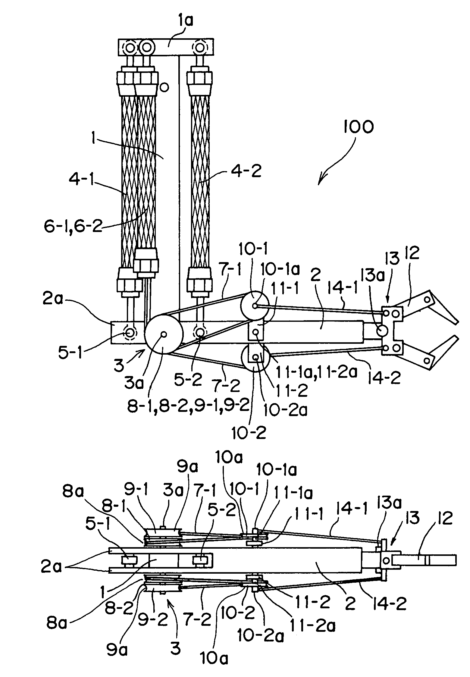
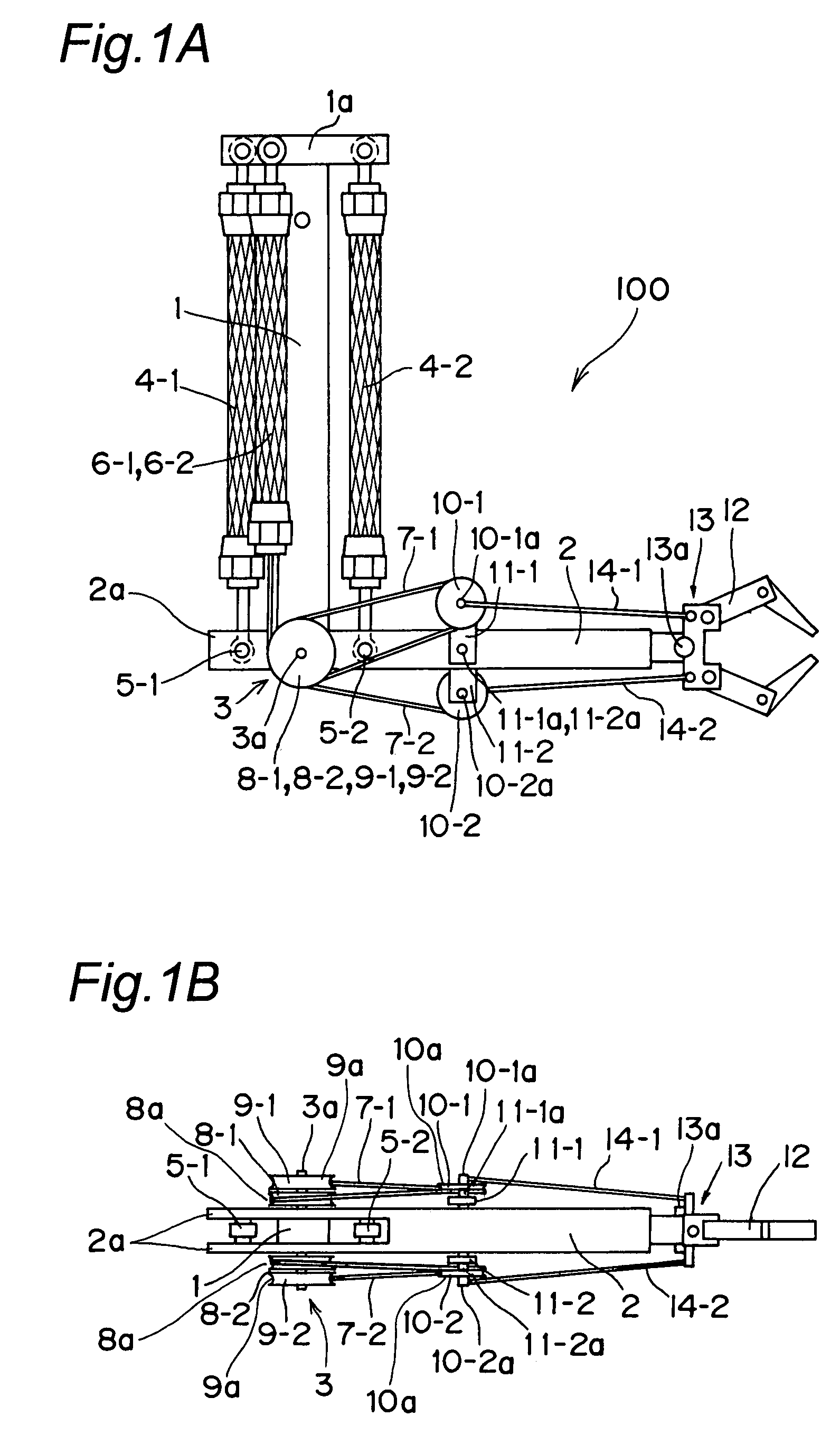
[0110]FIGS. 1A and 1B are overall views showing a joint structure according to a first embodiment of the present invention. FIGS. 1A and 1B show, by way of example, a structure of a case in which the joint structure of the first embodiment is applied to a robot arm 100.

[0111]In FIGS. 1A and 1B, numeral 1 designates a rod-shape first structure which forms an upper arm portion of the robot arm 100. Numeral 2 designates a rod-shape second structure which forms a front arm portion of the robot arm 100. The first structure 1 and the second structure 2 are connected to each other by a first revolute joint 3, and the first structure 1 and the second structure 2 can relatively forwardly and reversely be rotated about a joint shaft 3a of the first revolute joint 3. As an example shown in FIG. 1B, branch portions 2a into which a first revolute joint side-end portion of the second structure 2 is branched are formed, a lower end portion of the first structure 1 is sandwiched between the branch ...

second embodiment

[0139]FIG. 7 is a perspective view showing a detailed structure of a joint structure according to a second embodiment of the present invention. In FIG. 7, only main components will be described, and other configurations will be omitted because other configurations are similar to those of the First embodiment shown in FIGS. 1A and 1B. Although the wire is put round each pulley so as to be accommodated in each guide groove (similarly to FIG. 1B), the guide groove will be omitted in the following description and the corresponding drawing for the purpose of simplification.

[0140]In FIG. 7, numeral 23-1 designates a first movable rotating guide pulley, and numeral 24-1 designates a second movable rotating guide pulley. The first movable rotating guide pulley 23-1 and the second movable rotating guide pulley 24-1 have the same radius. The first movable rotating guide pulley 23-1 and the second movable rotating guide pulley 24-1 are fixed to each other, and the first movable rotating guide ...

third embodiment

[0145]FIG. 8 is a perspective view showing a detailed structure of a joint structure according to a third embodiment of the present invention. In FIG. 8, only main components will be described, and other configurations will be omitted because other configurations are similar to those of the First embodiment shown in FIGS. 1A and 1B. Although the wire is put round each pulley so as to be accommodated in each guide groove (similarly to FIG. 1B), the guide groove will be omitted in the following description and the corresponding drawing for the purpose of simplification.

[0146]The joint structure of the third embodiment differs from the joint structure of the first embodiment in the configuration of a fixed guide 29-1. The fixed guide 29-1 is formed not in the disk shape like the fixed guide pulleys 9-1 and 9-2 of the joint structure in the first embodiment, but only a neighborhood of the portion with which the arm flexure wire 7-1 comes into contact is formed in an arc shape, and a gro...


PUM


Abstract

A joint structure includes a rotating guide pulley, a fixed guide, and a rotating guide pulley. The rotating guide pulley is coaxial with a rotating shaft of a revolute joint, and is arranged so as to be rotatable about the rotating shaft. The fixed guide is arranged in a first structure, and has an arc portion. The arc portion has the same radius as the rotating guide pulley and is coaxial with the rotating guide pulley. The rotating guide pulley is arranged in a second structure so as to be relatively movable. A wire is put round the rotating guide pulley, the movable rotating guide pulley, and the fixed guide in the order of them.

Description

[0001]This is a continuation application of International Application No. PCT / JP2005 / 021239, filed Nov. 18, 2005.BACKGROUND OF THE INVENTION[0002]The present invention relates to a joint structure which can be applied to a joint mechanism of a mechanical apparatus such as a robot arm, and the robot arm including the joint structure.[0003]Conventionally, in a structure of a multiple-joint robot arm, an actuator which drives a joint is usually arranged in a joint portion or near the joint portion. However, in such a structure, hand inertia becomes large, because a heavy motor or the like is arranged near a hand such as a wrist of a human-like arm. This may hinder an improvement of hand position control performance, or may generate a large impact in collision, which requires a consideration in terms of safety.[0004]In response to the above issue, a wire drive type robot arm has been developed, in which the actuator is arranged near a base end position away from the driven joint and dri...

Claims


Application Information

Patent Timeline
Patent Type & Authority Patents(United States)
IPC IPC(8): B25J17/00
CPCB25J9/104B25J9/1075B25J9/142Y10T74/20329Y10T74/20323Y10T74/20335
Inventor OKAZAKI, YASUNAOASAI, KATSUHIKO
Owner PANASONIC CORP
Why Eureka
Try Eureka