Power conversion control with energy storage

Active Publication Date: 2011-09-15
GENERAL ELECTRIC CO
View PDF7 Cites 57 Cited by
  • Summary
  • Abstract
  • Description
  • Claims
  • Application Information

AI Technical Summary

Benefits of technology

[0004]It would be desirable to have an improved power conversion control embodiment for balancing the voltage on th

Problems solved by technology

These different control objectives for source and grid side control sometimes result in a power imbalance on the D

Method used


Image

  • Power conversion control with energy storage
  • Power conversion control with energy storage
  • Power conversion control with energy storage

Examples


Embodiment Construction

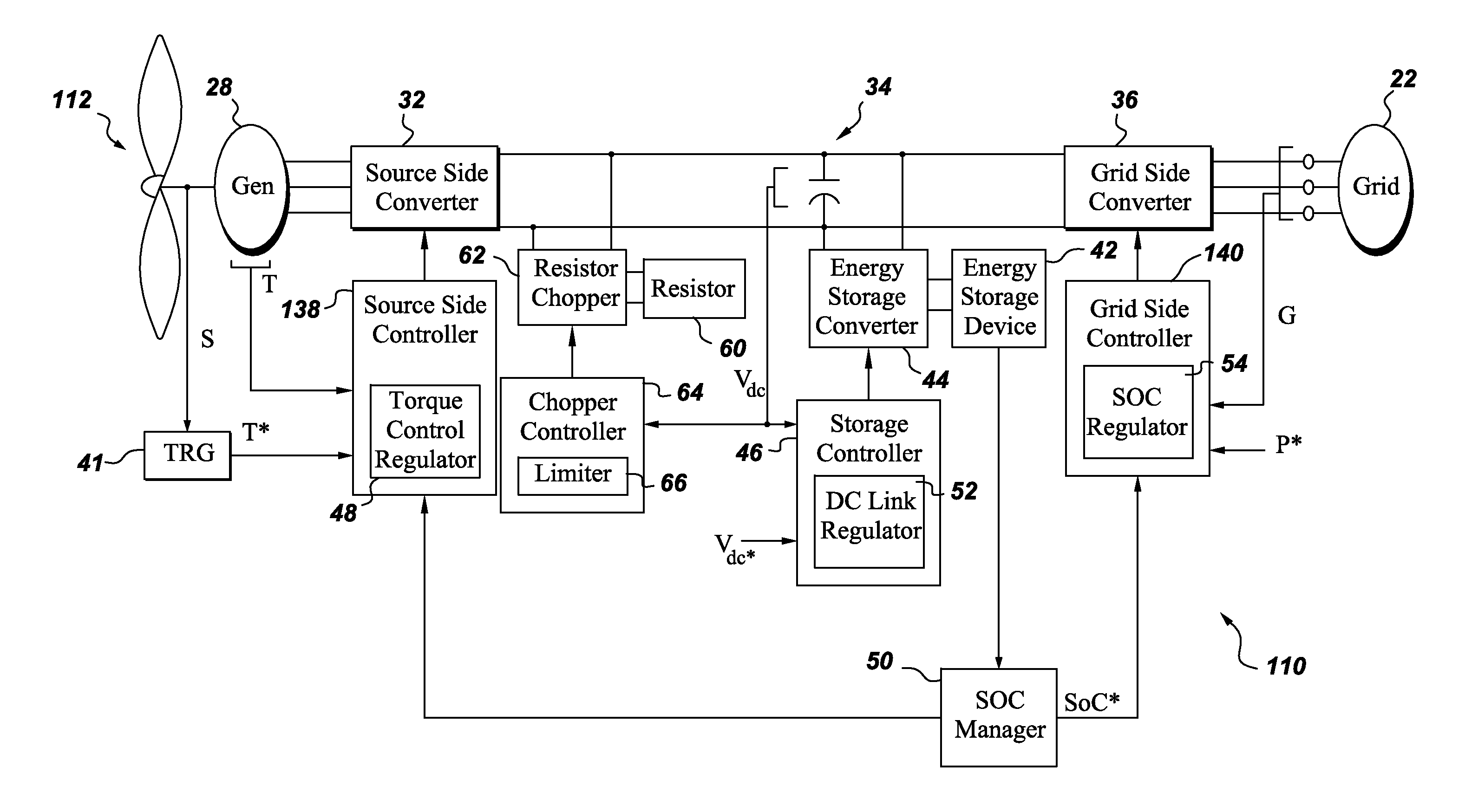
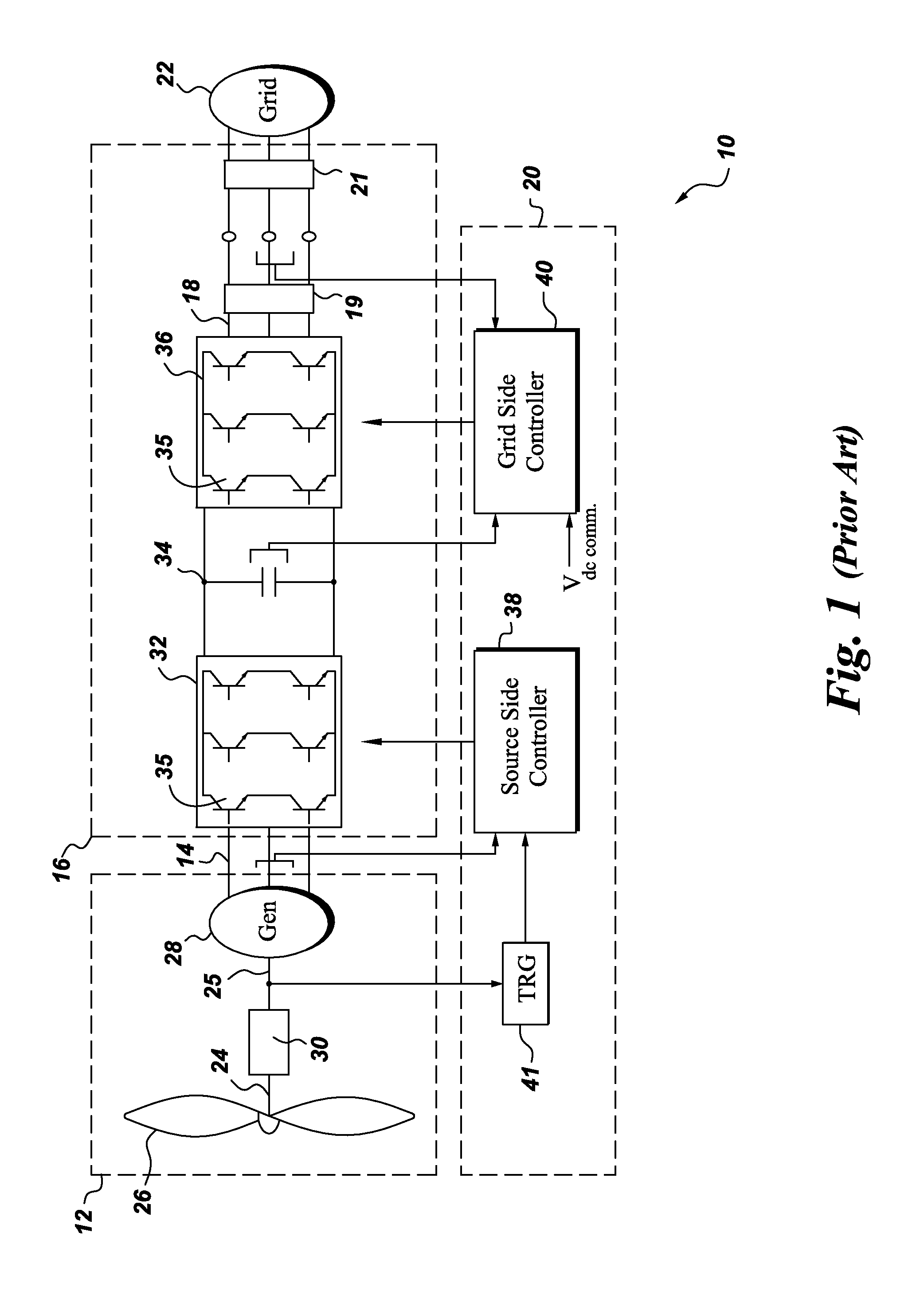
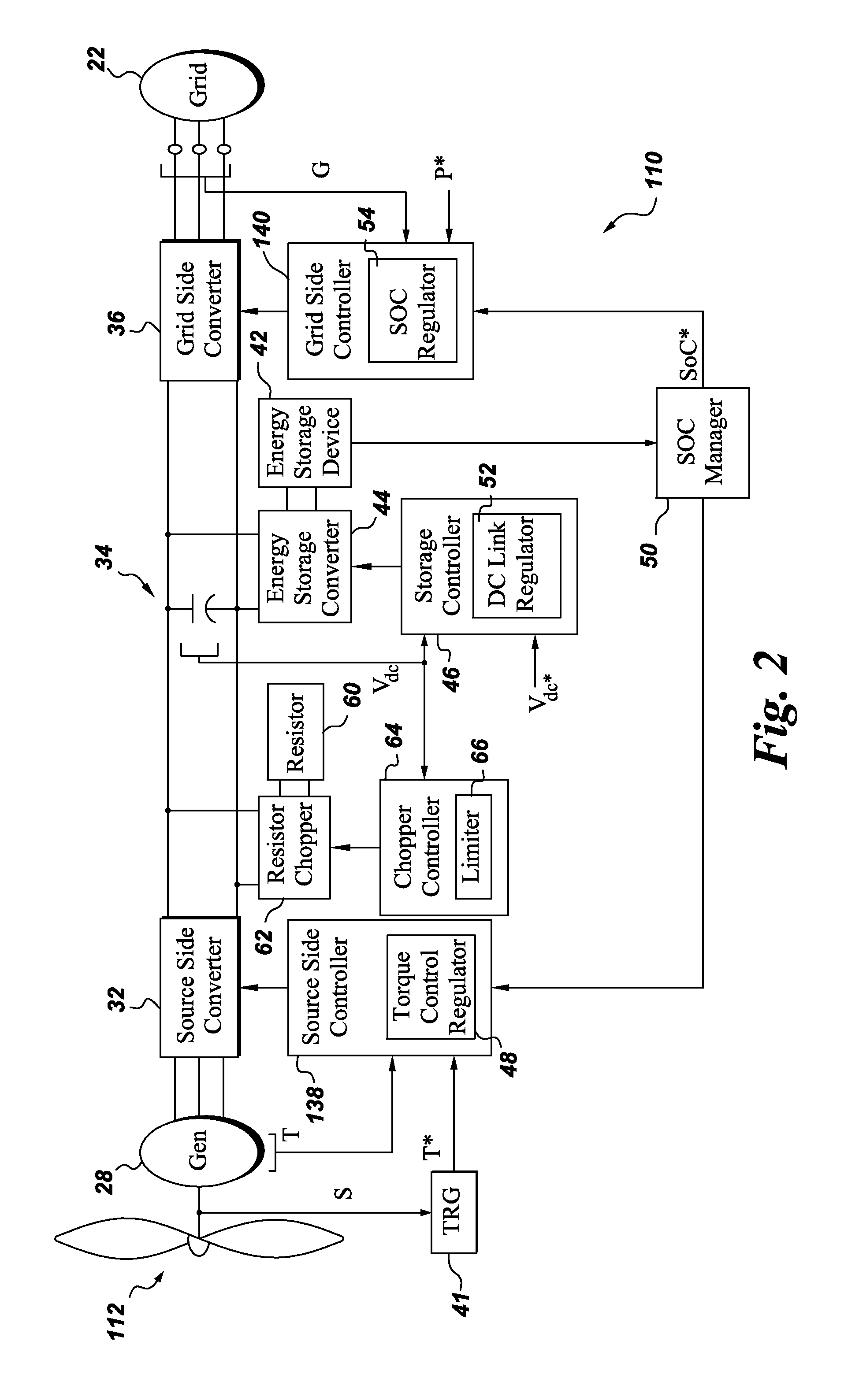
[0013]Reference is first made to a conventional renewable power generation system 10 as illustrated in FIG. 1. System 10 comprises a wind turbine generator 12 for generating an alternating current on phase conductors 14 with a variable frequency, a power conversion module 16 for converting the alternating current on phase conductors 14 into an alternating current on phase conductors 18, and a conventional power conversion control system 20 for receiving reference signals and commands for generating control signals for controlling operation of power conversion module 16. Alternating current on phase conductors 18 is further fed to an electric grid 22 with components such as filters 19 and transformers 21 typically being present along phase conductors 18. Although FIG. 1 illustrates a wind power generation system for purposes of example, embodiments of the invention are applicable to any renewable energy source with several other examples including solar and marine hydrokinetic energy...


PUM


Abstract

A power generation system includes a renewable power source for producing source power; a source side converter for converting the source power to converted DC power; a source side controller for driving the converted DC power towards a maximum power point; a DC link for receiving the converted DC power; a grid side converter coupled to the DC link for converting DC link power from the DC link to AC output power for a grid; a grid side controller for controlling the AC output power of the grid side converter to achieve grid interconnection requirements; an electrical energy storage device; an energy storage converter coupling the energy storage device to the DC link; an energy storage controller for controlling the energy storage converter to achieve a desired power balance on the DC link.

Description

BACKGROUND[0001]The subject matter disclosed herein relates generally to power conversion systems and more specifically to use of energy storage in conjunction with power conversion systems of renewable energy sources.[0002]In conventional control approaches for renewable energy sources with dual stage power conversion, a source side converter is coupled in parallel by DC (direct current) link to a grid side converter. In a wind turbine embodiment, for example, a source side controller uses wind turbine generator torque regulation to control the source side converter, and a grid side controller uses DC voltage regulation to control the grid side converter. Other examples of renewable energy sources include solar and marine hydrokinetic energy sources.[0003]A goal of the source side controller when providing power from a renewable energy source is to transmit as much of the source power to the grid as possible, whereas a goal of the grid side converter is to satisfy grid interconnect...

Claims


Application Information

Patent Timeline
IPC IPC(8): H02M5/45
CPCH02J3/32Y02E10/763Y02E70/30H02J3/386H02J2300/20H02J3/381H02J2300/24H02J2300/28Y02E10/56
Inventor DELMERICO, ROBERT WILLIAMYUAN, XIAOMING
Owner GENERAL ELECTRIC CO
Why Eureka
Try Eureka