Gear-shifting structure for vehicle

a technology for gear shifting and vehicles, applied in mechanical actuators, gear shifting, mechanical apparatus, etc., can solve the problems of high cost caused by the number of parts, increase the cost of parts, and delay in the time of successive gear shifting operations, so as to reduce the number of parts of the gear shifting structure, increase the flexibility of design, and reduce the effect of cost reduction

Inactive Publication Date: 2009-12-17
KYMCO
View PDF5 Cites 20 Cited by
  • Summary
  • Abstract
  • Description
  • Claims
  • Application Information

AI Technical Summary

Benefits of technology

[0009]The primary purpose of the present invention is to provide a gear-shifting structure for a vehicle, wherein the vehicle comprises a transmission box that contains therein a gear train, a clutch, a switching fork, a gear-shifting hub, and a motor. The motor cooperates with a worm shaft to actuate the clutching operation of the clutch and to cause movement of the gear-shifting hub in order to carry out the gear shifting operation. The motor has a rotary member that drives the worm shaft on which a worm and a cam are mounted. To effect gear shifting, the motor drives the worm shaft to have the cam abut and displace the clutch and at the same time, the worm drives the gear-shifting hub to thus realize the operation of gear shifting. Thus, the number of parts of the gear-shifting structure is reduced, which leads to effective reduction of cost of the gear-shifting structure and also increases the flexibility of design and further, the use of the interior space of the transmission box is subjected to less constraint caused by the arrangement of the gear-shifting structure and / or expansion of the size of the transmission box due to the constraint set by the arrangement of the gear-shifting structure can be alleviated.
[0010]Another objective of the present invention is to provide a gear-shifting structure for a vehicle, wherein with the engagement between a worm of a worm shaft and a worm gear of the gear-shifting hub, precision and smoothness of gear shifting operation can be enhanced.

Problems solved by technology

This causes an undesired constraint to the utilization of space and installing two sets of operator and motor also leads to increase of costs.
The adoption of a single motor as described above, although effective in solving the problems related to spatial arrangement and costs, yet is disadvantageous in that to complete a gear shifting operation, the motor has to take operation for both forward and backward rotation.
This leads to a delay in time in performing successive gear shifting operations.
In addition, there still needs a number of parts and thus the problems of high costs caused by the number of parts have not been yet solved.
Further, the utilization of the space inside a transmission is still subjected to undesired constraint so that expanding the size of the gear box is inevitable.
In addition, the rocker arm uses the force from the ratcheting member spring to drive a clutch cam, and this leads to poor linearility of the clutch cam.
In addition, transmission through the rocker arm also results in poor accumulated precision from the motor to the clutch cam.
In case of successive operations of gear shifting, the spring may not respond sufficiently quickly so that the successive operation of gear shifting for this type of gear-shifting system is subjected to constraint.

Method used


Image

  • Gear-shifting structure for vehicle
  • Gear-shifting structure for vehicle
  • Gear-shifting structure for vehicle

Examples


Embodiment Construction

[0016]The following descriptions are of exemplary embodiments only, and are not intended to limit the scope, applicability or configuration of the invention in any way. Rather, the following description provides a convenient illustration for implementing exemplary embodiments of the invention. Various changes to the described embodiments may be made in the function and arrangement of the elements described without departing from the scope of the invention as set forth in the appended claims.

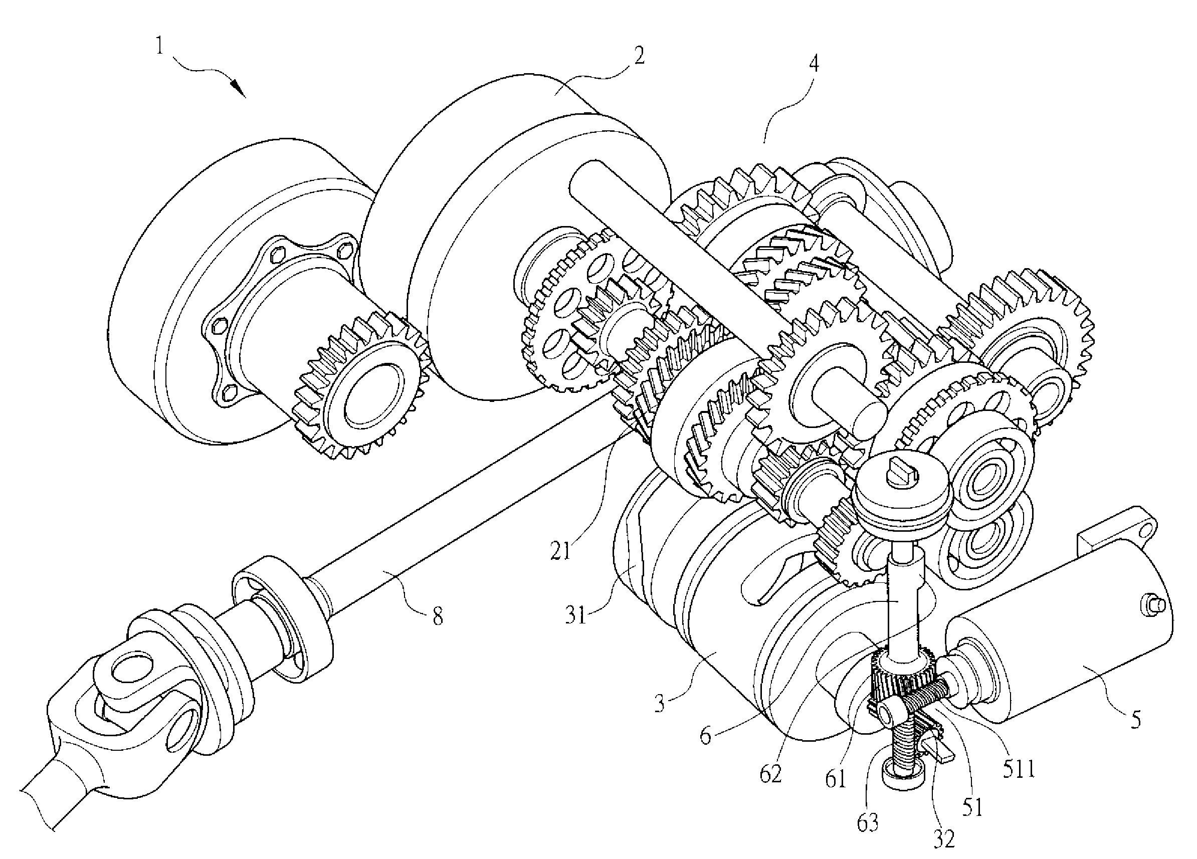
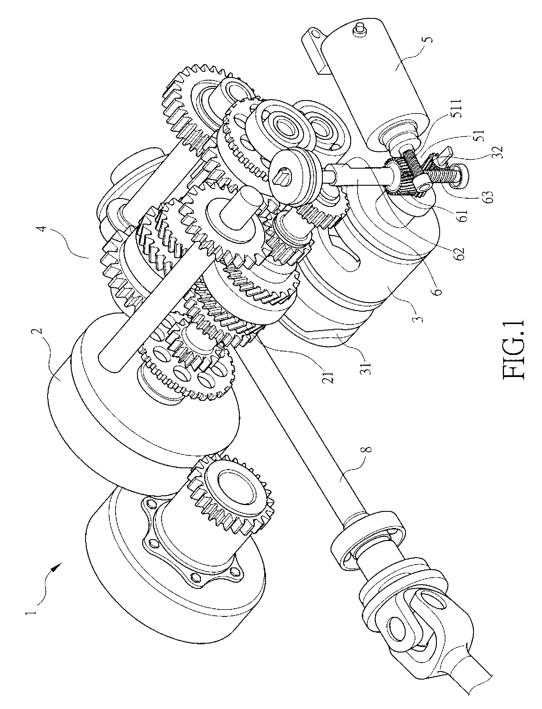
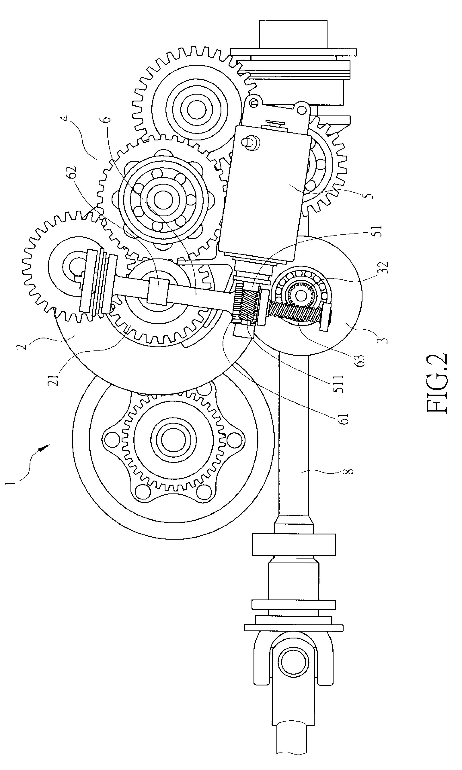
[0017]The present invention relates to a gear-shifting structure for a vehicle, which comprises a power unit that is comprised in part of a transmission box 1. With reference to FIGS. 1, 2, and 3, the transmission box 1 contains therein at least a clutch 2, a gear-shifting hub 3, a gear train 4, a motor 5, a worm shaft 6, and a switching fork 7.

[0018]The clutch 2 is driven by the power supplied from a crankshaft (not shown) of the power unit and the clutch 2 is in engagement with gear train 4 to ...


PUM


Abstract

A gear-shifting structure is provided for a vehicle. The vehicle includes a transmission box that contains therein a gear train, a clutch, a switching fork, a gear-shifting hub, and a motor. The motor cooperates with a worm shaft to actuate the clutching operation of the clutch and to cause movement of the gear-shifting hub in order to carry out the gear shifting operation. The motor has a rotary member that drives the worm shaft on which a worm and a cam are mounted. To effect gear shifting, the motor drives the worm shaft to have the cam abut and displace the clutch and at the same time, the worm drives the gear-shifting hub to thus realize the operation of gear shifting.

Description

BACKGROUND OF THE INVENTION[0001](a) Technical Field of the Invention[0002]The present invention relates to a gear-shifting structure for a vehicle, and in particular to a gear-shifting structure that integrates the operation of a clutch contained in a transmission box and a power source of gear shifting carried out by a gear-shifting hub.[0003](b) Description of the Prior Art[0004]For a currently-available vehicle that is equipped with the so-called automated manual transmission (AMT), the operation of gear shifting is done by controlling an automatic clutching operator of a transmission box to cause disengagement or release of a clutch, followed by an automatic gear-shifting operator causing rotation of a gear-shifting hub to carry out gear shifting. Both the clutch and the gear-shifting hub are individually provided with an operator and a motor for carrying out the operation thereof. Thus, an AMT mechanism needs at least two sets of operator and motor. This causes an undesired co...

Claims


Application Information

Patent Timeline
Patent Type & Authority Applications(United States)
IPC IPC(8): F16D23/00
CPCF16D28/00F16H61/32Y10T74/19828F16H63/46Y10T74/19279F16H63/18
Inventor LAI, CHIEN-HUNGHO, CHAO-CHANG
Owner KYMCO
Why Eureka
Try Eureka