Wired circuit board

a wired circuit board and circuit technology, applied in the field of wired circuit boards, can solve the problems of inability to compactize suspension boards with circuits formed by insulating layers, and the likelihood of short circuits between them, so as to improve the reliability of connection and enhance flexibility in design

Inactive Publication Date: 2013-01-24
NITTO DENKO CORP
View PDF1 Cites 51 Cited by
  • Summary
  • Abstract
  • Description
  • Claims
  • Application Information

AI Technical Summary

Benefits of technology

[0019]This can enhance flexibility in designing the layout of the first connecting portion and the second connecting portion and also allow the first terminal and the second terminal which are continued thereto to be formed at respect

Problems solved by technology

Accordingly, on such an insulating layer, the magnetic head terminals and the actuator terminals should be formed at high densities, resulting in a problem that a short circuit is lik

Method used


Image

  • Wired circuit board
  • Wired circuit board
  • Wired circuit board

Examples


first embodiment

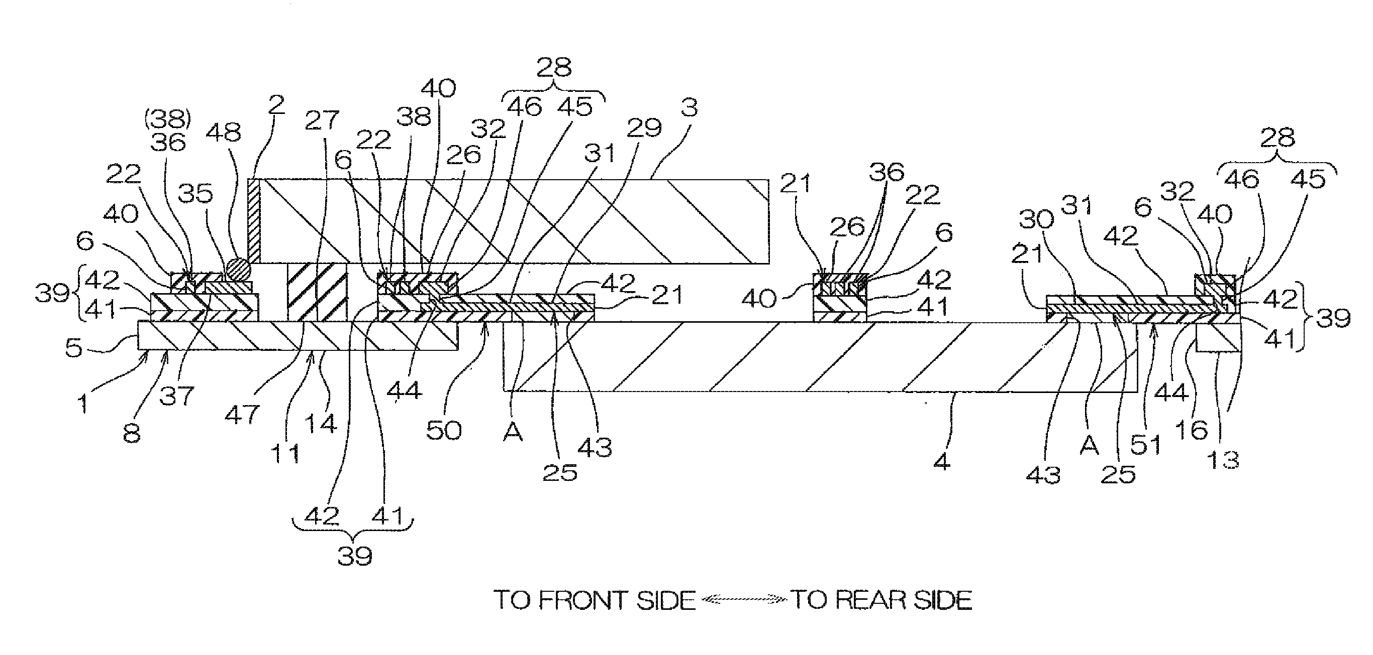
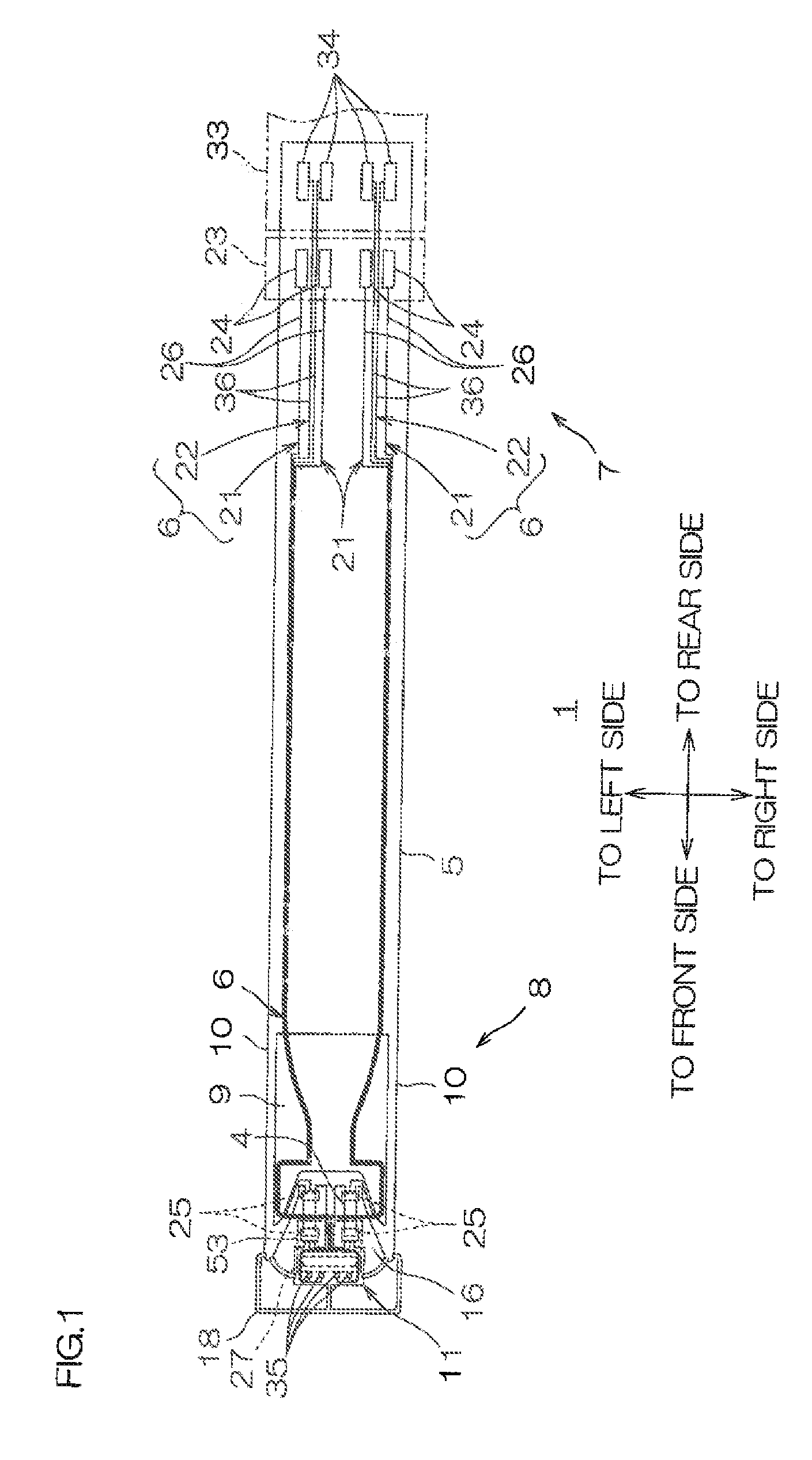
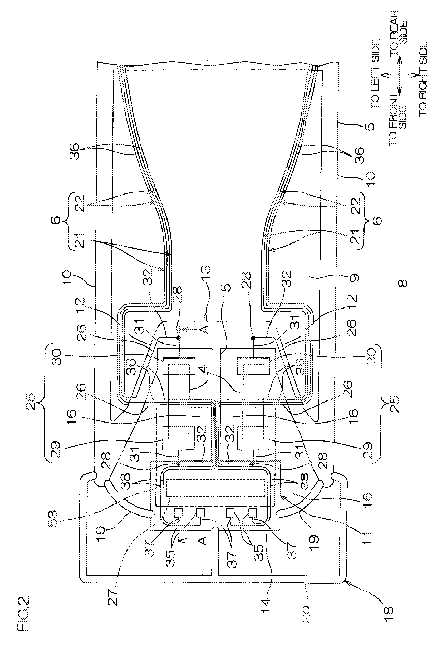
[0081]FIG. 1 shows a plan view of a suspension board with circuit as a first embodiment (a form in which element-wire supply-side portions and head-wire outer portions are formed on a second insulating base layer) of a wired circuit board of the present invention. FIG. 2 shows an enlarged plan view of a gimbal portion of the suspension board with circuit shown in FIG. 1. FIG. 3 shows a crass-sectional along the line A-A of the gimbal portion shown in FIG. 2. FIG. 4 shows an enlarged plan view of the gimbal portion shown in FIG. 2, which is a plan view in which an insulating cover layer is omitted. FIG. 5 shows an enlarged plan view of the gimbal portion shown in FIG. 2, which is a plan view in which the second insulating base layer, first conductive patterns and second conductive patterns each formed thereon, and the insulating cover layer are omitted. FIGS. 6 and 7 are process views each for illustrating a producing method of the suspension board with circuit shown in FIG. 1. FIG. ...

second embodiment

[0202]Referring to FIGS. 9 to 13, a second embodiment of the suspension board with circuit is described. Note that, in FIGS. 9 to 13, the same members as used in the first embodiment described above are designated by the same reference numerals, and a detailed description thereof is omitted.

[0203]FIG. 9 shows an enlarged plan view of the gimbal portion of the suspension board with circuit as the second embodiment (a form in which element-wire supply-side portions and head-wire outer portions are formed on a first insulating base layer) of the wired circuit board of the present invention. FIG. 10 shows a cross-sectional view along the line B-B of the gimbal portion shown in FIG. 9. FIG. 11 shows a perspective view of head-side connecting portions. FIG. 12 is a process view for illustrating a producing method of the suspension board with circuit shown in FIG. 9.

[0204]Note that, in FIG. 11, the insulating cover layer 40 is omitted for clear illustration of relative positioning of the i...

third embodiment

[0226]Referring to FIGS. 14 to 16, a third embodiment of the suspension board with circuit is described. Note that, in FIGS. 14 to 16, the same members as used in the first embodiment described above are designated by the same reference numerals, and a detailed description thereof is omitted.

[0227]FIG. 14 shows a cross-sectional view of the gimbal portion of the suspension board with circuit as the third embodiment of the wired circuit board of the present invention. FIGS. 15 and 16 are process views for illustrating a producing method of the suspension board with circuit shown in FIG. 14.

[0228]In the first embodiment described above, the projecting end portion 49 of the front-side projecting portion 50 and the projecting end portion 49 of the rear-side projecting portion 51 are each formed in a generally rectangular frame plan view shape, and the front element-side terminals 29 and the rear element-side terminals 30 are formed so as to be downwardly fitted in the frames of the corr...


PUM


Abstract

A wired circuit board includes an insulating layer, and a conductive layer formed on the insulating layer. The insulating layer includes a first insulating layer, and a second insulating layer formed on the first insulating layer. The conductive layer includes a first conductive pattern, and a second conductive pattern. The first conductive pattern includes a first connecting portion formed on the first insulating layer and under the second insulating layer, and at least one pair of first terminals configured continuously to the first connecting portion so as to electrically connect to an external electronic element and spaced apart from each other to allow the electronic element to extend therebetween. The second conductive pattern includes a second connecting portion formed on the second insulating layer, and a second terminal configured continuously to the second connecting portion so as to electrically connect to a magnetic head provided on an external slider.

Description

CROSS-REFERENCE TO RELATED APPLICATION[0001]The present application claims the benefit of U.S. Provisional Application No. 61 / 573,075 filed on Aug. 26, 2011, and claims priority from Japanese Patent Applications No. 2011-159688 filed on Jul. 21, 2011 and Japanese Patent Applications No. 2011-180971 filed on Aug. 22, 2011, the contents of which are hereby incorporated by reference into this application.BACKGROUND OF THE INVENTION[0002]1. Field of the Invention[0003]The present invention relates to a wired circuit board, and particularly to a wired circuit board used suitably as a suspension board with circuit used in a hard disk drive.[0004]2. Description of the Related Art[0005]A suspension board with circuit includes a metal supporting board, an insulating base layer formed thereon, and a conductive pattern formed thereon and having head-side terminals for connecting to a magnetic head. In the suspension board with circuit, a magnetic head is mounted and connected to a head-side te...

Claims


Application Information

Patent Timeline
IPC IPC(8): H05K1/02H05K1/05
CPCH05K1/056G11B5/486G11B5/4853
Inventor OHSAWA, TETSUYA
Owner NITTO DENKO CORP
Why Eureka
Try Eureka