Multi-beam optical scanner

Inactive Publication Date: 2003-07-22
RICOH KK
View PDF8 Cites 12 Cited by
  • Summary
  • Abstract
  • Description
  • Claims
  • Application Information

AI Technical Summary

Benefits of technology

It is an object of the present invention to effectively reduce degradation in image quality in a recorded image due to pitch deviation, in addition, to enable effective reduction of cost of a l

Problems solved by technology

In the interlace scanning as described above, selection of a signal for modulating each beam is irregular, so that optical scanning is easily complicated, and in addition, scanning lines for optically concurrently scanning are also largely spaced therebetween, so that "a rate of pitch deviation" of optical scanning due to a bend in the scanning lines becomes large, which makes it easy for image quality of a recorded image to degrade.
In the multi-beam optical scanner, there are strict restriction over a magnification in an image-formation system provided in a space between the light source and the surface for scanning due to a relation between pitches of scanning lines, and because of the restrictions over a magnification as described above, a position of an optical system to be provided in a side of the light source from the optical deflector must be closer to the optical deflector, and for this reason, a layout of optical arrangement becomes difficult.
Further, if a "hybrid"

Method used


Image

  • Multi-beam optical scanner
  • Multi-beam optical scanner
  • Multi-beam optical scanner

Examples


Embodiment Construction

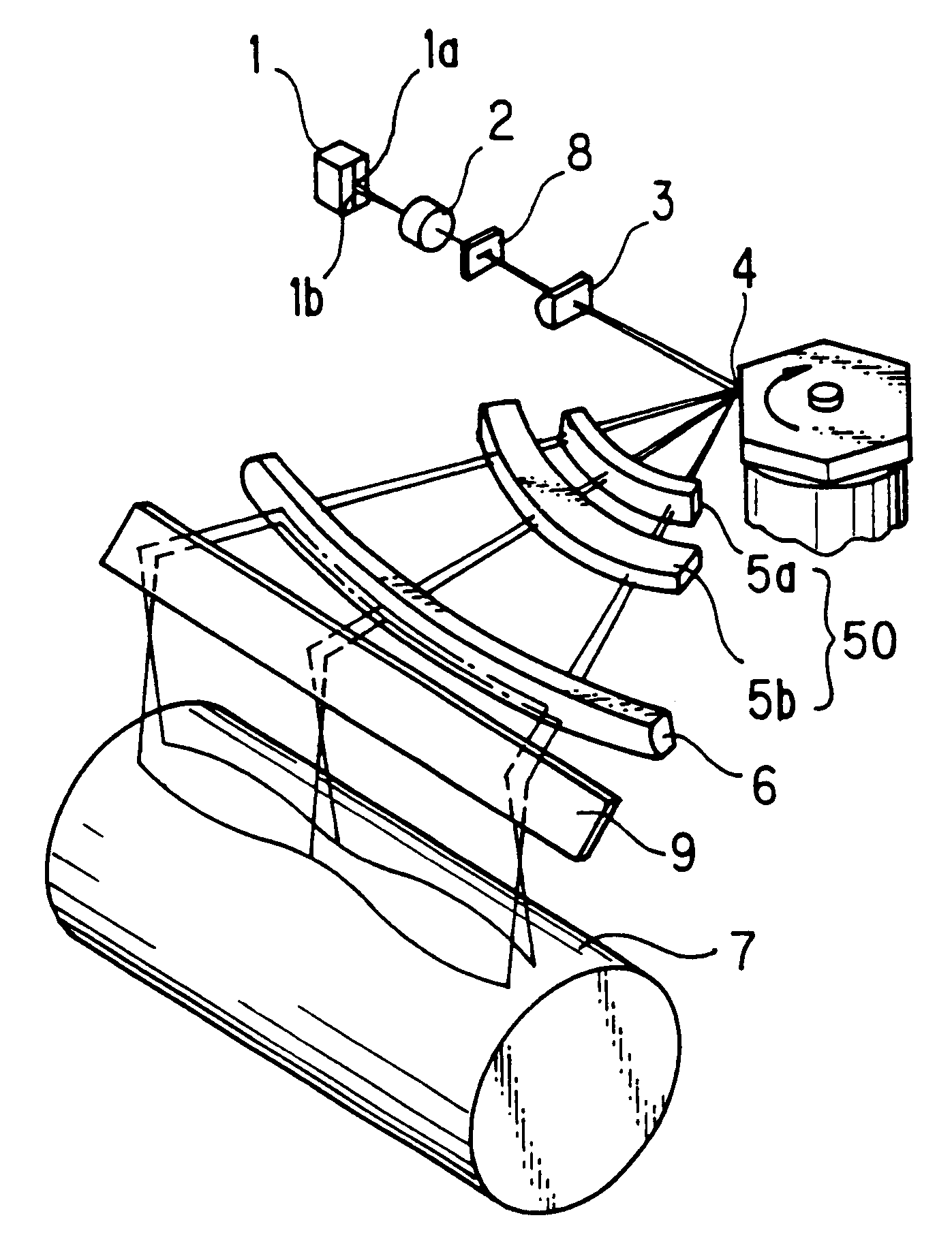
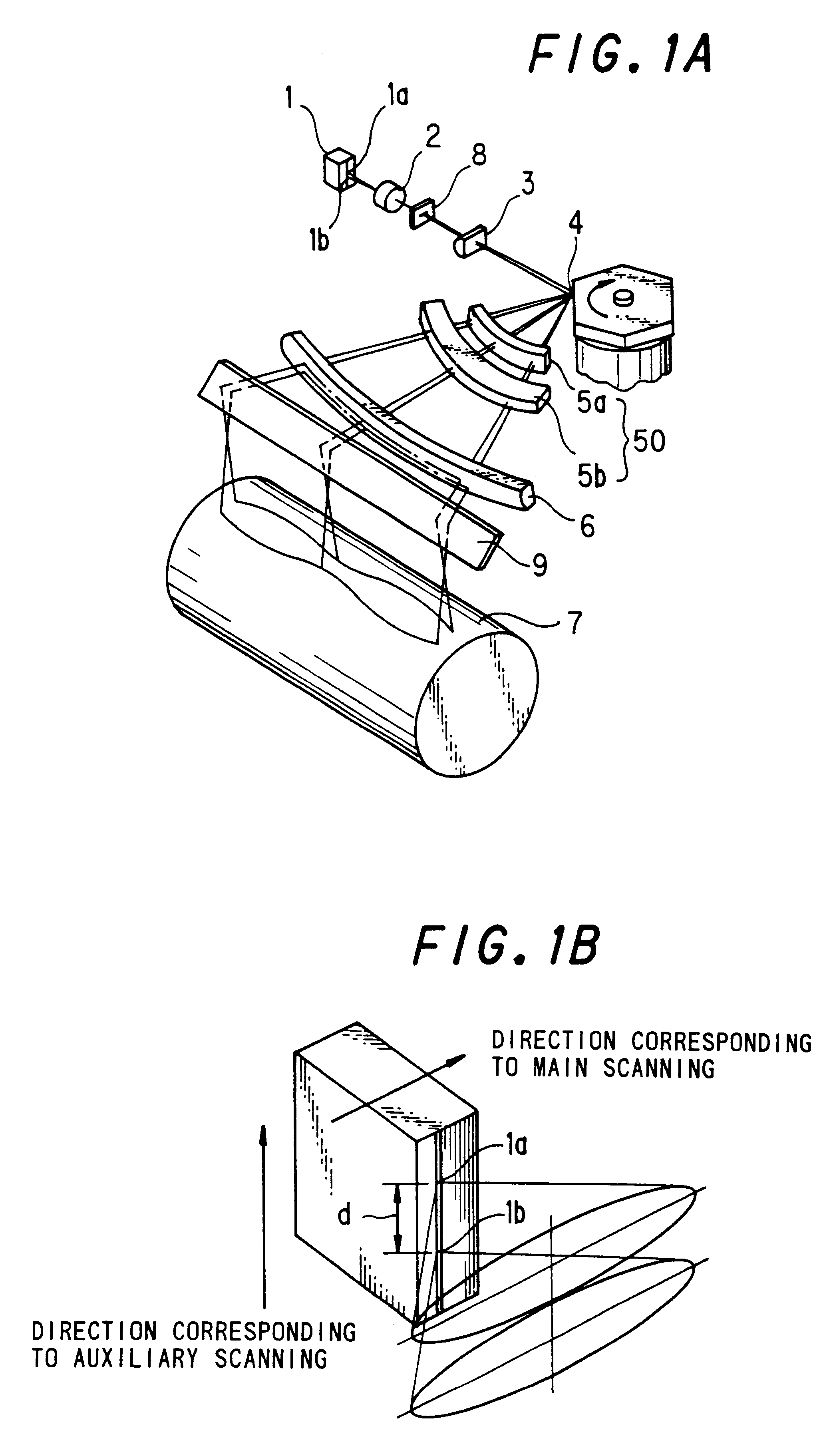
In FIG. 1A, a light source 1 for a multi-beam is, as shown in FIG. 1B, a monolithic semiconductor laser having two LD light emitting sections 1a and 1b provided therein so that the two light emitting sections 1a, 1b are arranged with a space d in a direction corresponding to the auxiliary scanning.

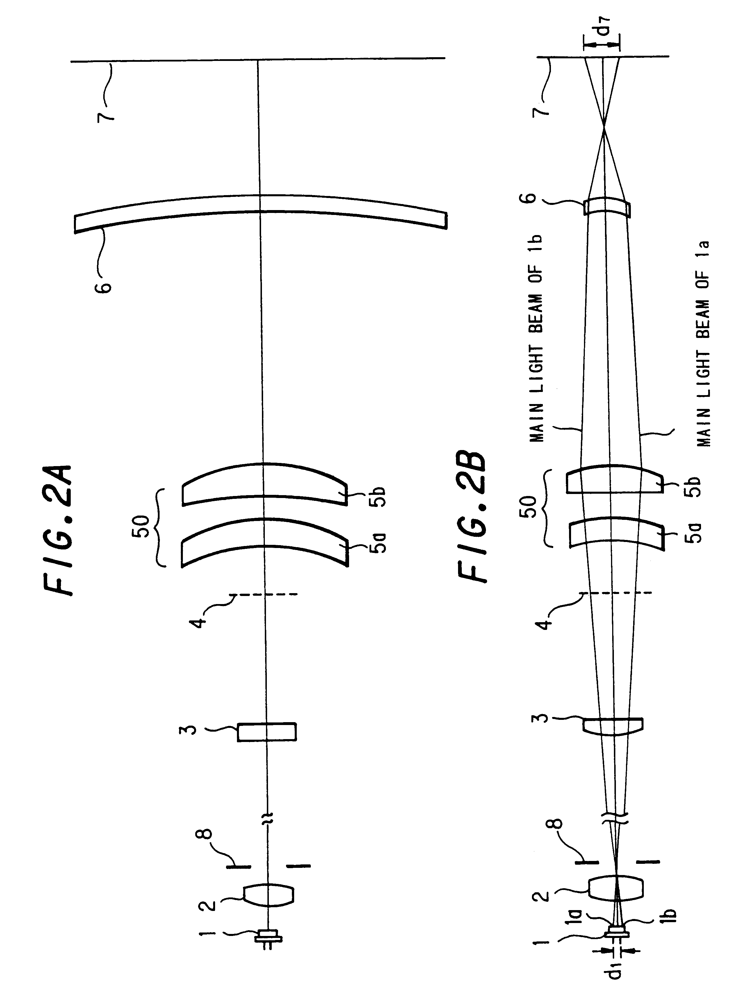
In FIG. 1A, both of two light fluxes radiated from the two LD light emitting sections 1a and 1b in the light source 1 for a multi-beam are converted to parallel ones by a collimate lens 2. The LD light emitting sections 1a and 1b in the light source 1 for a multi-beam are provided at positions each at an equal distance (d / 2) from the optical axis of the collimate lens 2 respectively.

The two light fluxes radiated from the collimate lens 2 are cut off in each of peripheral sections of the light fluxes by an aperture 8 for beam formation to enter a cylinder lens 3 as a first image-formation system.

The cylinder lens 3 has positive power only in a direction corresponding to the auxiliary scanni...


PUM


Abstract

A multi-beam optical scanner, in which a lateral magnification beta in a composite system of an optical system between the light source for a multi-beam and the scanned surface satisfies the condition: 2<beta<=8.5, and a plurality of light spots on the scanned surface execute optical scanning of the scanning lines adjacent to each other.

Description

BACKGROUND OF THE INVENTIONThe present invention relates to a multi-beam optical scanner and more particularly to a multi-beam optical scanner realizing a light spot in an appropriate form on a scanned surface and effectively reducing degradation in image quality of a recorded image due to pitch deviation.BACKGROUND OF THE INVENTIONAn optical scanner has been known in relation to an image forming apparatus, such as a digital copying machine, an optical printer, and an optical printing machine or the like. In the optical scanner as described above, there has been proposed a multi-beam optical scanning system for optically and concurrently scanning an image with a plurality of scanning lines for the purpose of speeding up an operation for writing images by way of optical scanning.In the multi-beam optical scanning system, there is sometimes a case where scanning lines for optically and concurrently scanning are not adjacent to each other. There has been proposed, for instance, in Japa...

Claims


Application Information

Patent Timeline
IPC IPC(8): G02B26/12B41J2/44G02B13/18G02B13/24G02B26/10H04N1/113
CPCG02B26/123
Inventor SAKAI, KOHJIAOKI, MAGANE
Owner RICOH KK
Why Eureka
Try Eureka