Client server system

a client server and server technology, applied in the field of client server system, can solve the problems of a method relying on the scaling function of the display device, and a problem, so as to facilitate the sending of image information without causing an uncomfortable feeling for users

Inactive Publication Date: 2011-04-12
FUNAI ELECTRIC CO LTD
View PDF24 Cites 31 Cited by
  • Summary
  • Abstract
  • Description
  • Claims
  • Application Information

AI Technical Summary

Benefits of technology

[0010]An object of the present invention is to provide a client server system that can more easily send image information corresponding to the screen resolution of the display device connected to the client terminal device from the server device, and can display the image information in the display device without causing a user have an uncomfortable feeling.
[0013]That is, the server device can determine the resolution of the image information which is to be sent to the client terminal device, within taking into account the screen resolution of the display device connected to the client terminal device. Meantime, the resolution conversion section provided at the server device is only the server resolution conversion section that converts the image information of the first resolution into image information of the second resolution. Therefore, the decrease in image quality displayed I the display device can be kept to minimum, and the cost of the server device can be suppressed.
[0015]Therefore, the client terminal device does not have to check the resolution of the image information sent from the server device, thus excellent efficiency is achieved.
[0021]That is, the server device can determine the resolution of the image information which is to be sent to the client terminal device, within taking into account the client terminal device. Meantime, the resolution conversion section provided at the server device is only the server resolution conversion section that converts the image information of the first resolution into image information of the second resolution. Therefore, the decrease in image quality displayed I the display device can be kept to minimum, and the cost of the server device can be suppressed.
[0023]Therefore, the client terminal device does not have to check the resolution of the image information sent from the server device, thus excellent efficiency is achieved.

Problems solved by technology

However, method relying on the scaling function of the display device has a problem.
For example, size of an image displayed on the display device becomes smaller than the screen size of the display device once, and then becomes aligned to the screen size of the display device, thus a person observing the display device have an uncomfortable feeling.
In particular, for example, in case the resolution of the image information changes while sending the image information, in other words, in case an image information sending rate decreases even though the server device has sent to the client terminal device an image information with high definition (HD) image information, or in case sending an image information of standard definition (SD) image information becomes necessary due to an increase in number of client terminal device to which the image information is sent, the size of an image displayed in the display device becomes unmatched with the screen size of the display device in mid-course, thus causing a person observing the display device have an uncomfortable feeling.
Therefore, a problem arises in that even though the client terminal device displays on the display device with screen resolution of HD, the SD image information converted into HD image information, image quality is degraded compared to a case when HD image information sent from the server device is displayed as it is.
However, in such method, the server device needs to have a structure that can send HD image information and SD image information individually in accordance with the screen resolution of each display device, and results in high cost.
Thus, it is not efficient.

Method used


Image

  • Client server system
  • Client server system
  • Client server system

Examples


Embodiment Construction

[0034]An embodiment of the present invention will be described in detail hereinbelow with reference to figures. However, the scope of the invention shall not be limited to examples shown in figures.

[0035]First of all, structure of client server system, server device, and client terminal device is described.

[Structure of Client Server System]

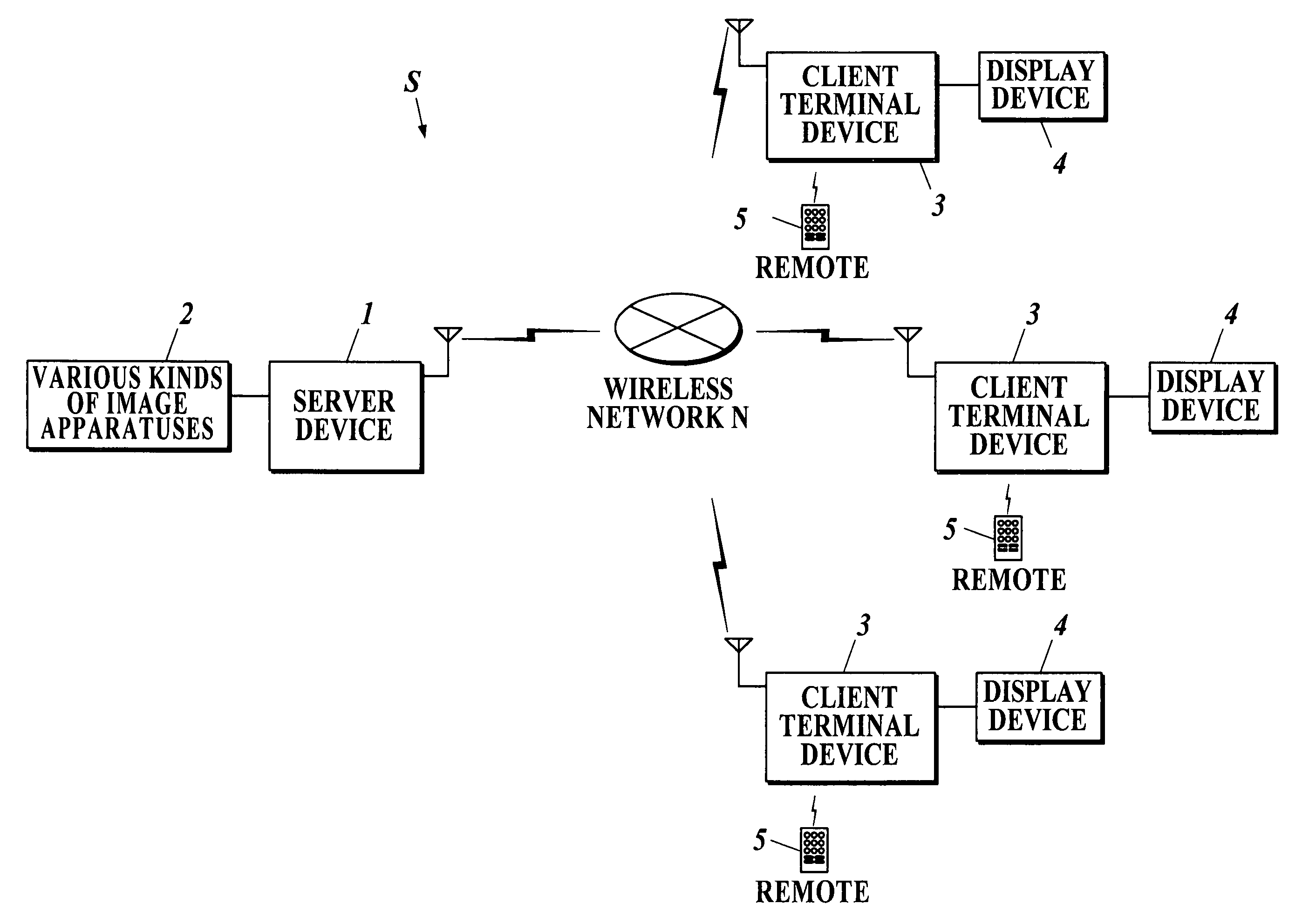
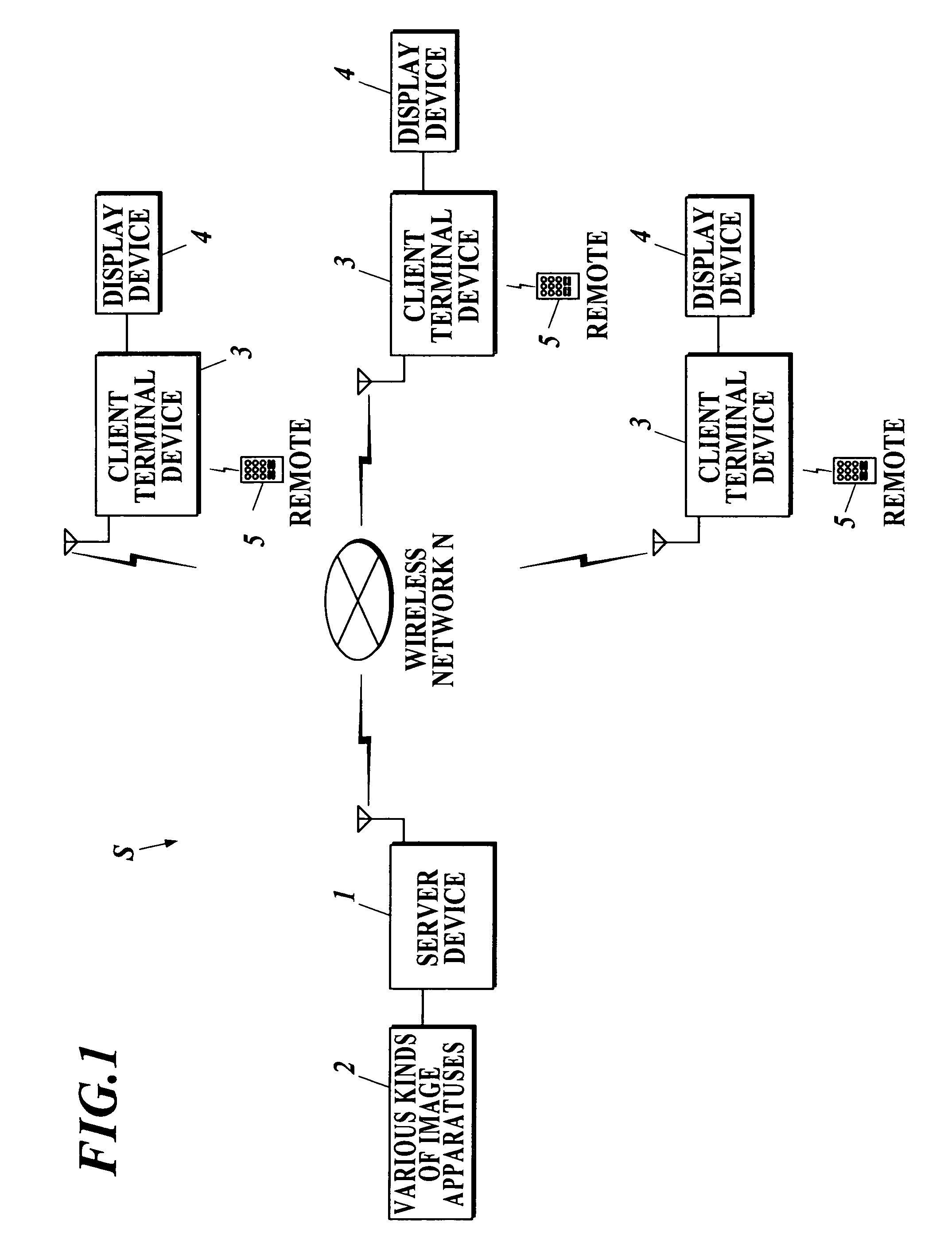
[0036]As shown in FIG. 1, client server system S is capable to connect with a server device 1 connected with various kinds of image apparatuses 2 and a display device 4, and is structured with a plurality of client terminal devices 3 that can be operated with remote controller 5 (hereinafter referred to as remote 5), and the like, for example. The server device 1 and the client terminal device 3 is connected through a wireless network N, and can send and receive information mutually.

[0037]Here, number of client terminal device 3 for the server device 1 is not limited to that in FIG. 1.

[0038]As for information sent from the client terminal device ...


PUM


Abstract

A client server system S includes a plurality of client terminal devices 3 capable to connect with display device 4, whose screen resolution is HD or SD, and a server device which provides image information to the plurality of client terminal devices s through wireless network N. The server device 1 is structured to include a sendable resolution determining program 1134 to make CPU 111 determine whether to convert HD image information into SD image information or not, and an image information sending program 1135 to make the CPU 111 send SD image information attached with SD information to the plurality of client terminal devices 3.

Description

BACKGROUND OF THE INVENTION[0001]1. Field of the Invention[0002]The present invention relates to a client server system.[0003]2. Description of the Related Art[0004]Recently, a system that sends and provides image information (contents information) from a server device to a client terminal device them through a network is utilized. To the server device, a plurality of types of image apparatuses such as a television device, a video recorder, a personal video recorder (PVR), a tuner for broadcasting satellite (BS) and communication satellite (CS), a set top box (STB), a digital versatile disk (DVD) player, and the like, are connected for example. The server device is capable to send image information corresponding to the image apparatus connected to the server device, to the client terminal device.[0005]In case resolution of the image information sent from the server device is different from a screen resolution of a display device connected to the client terminal device, the resolutio...

Claims


Application Information

Patent Timeline
Patent Type & Authority Patents(United States)
IPC IPC(8): G06F3/12G06F15/16H04N7/18H04N7/173G06F13/00H04N21/2343
CPCH04N21/234363H04N21/25825H04N21/6582H04N21/6377H04N21/658H04N21/2662
Inventor HIROOKA, SATOSHI
Owner FUNAI ELECTRIC CO LTD
Why Eureka
Try Eureka