Image signal processing method, image signal processing system, storage medium, and image sensing apparatus

Inactive Publication Date: 2005-05-24
OHMI +8
View PDF11 Cites 30 Cited by
  • Summary
  • Abstract
  • Description
  • Claims
  • Application Information

AI Technical Summary

Benefits of technology

[0018]Accordingly, it is an object of the present invention to provide an image signal processing method and image signal processing system, which can greatly reduce the data size upon transmitting an image signal or storing the signal

Problems solved by technology

However, deterioration of image quality due to block noise and high-frequency noise produced upon information compression cannot be avoided.
However, when a

Method used


Image

  • Image signal processing method, image signal processing system, storage medium, and image sensing apparatus
  • Image signal processing method, image signal processing system, storage medium, and image sensing apparatus
  • Image signal processing method, image signal processing system, storage medium, and image sensing apparatus

Examples


first embodiment

(First Embodiment)

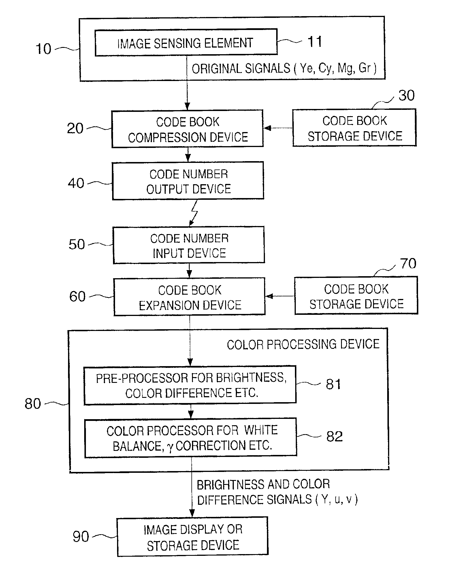
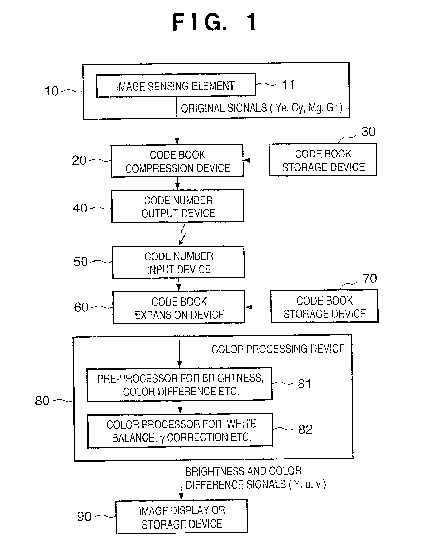
[0054]FIG. 1 is a block diagram for explaining the first embodiment of the present invention. As shown in FIG. 1, the image signal transmitting side of the image signal processing system of this embodiment is constituted by an image sensing element IC chip (to be referred to as an image sensing unit hereinafter) 10, code book compression device 20, code book storage device 30, and code number output device 40.

[0055]The image signal receiving side is constituted by a code number input device 50, code book expansion device 60, code book storage device 70, color processing device 80, and image display or storage device 90.

[0056]The image sensing unit 10 has an image sensing element (light-receiving element) 11. In this embodiment, three complementary color filters and one primary color filter, i.e., cyan, yellow, magenta, and green filters are set on the image sensing element 11. Hence, the image sensing element 11 serially outputs original signals Ye, Cy, Mg, and Gr....

second embodiment

(Second Embodiment)

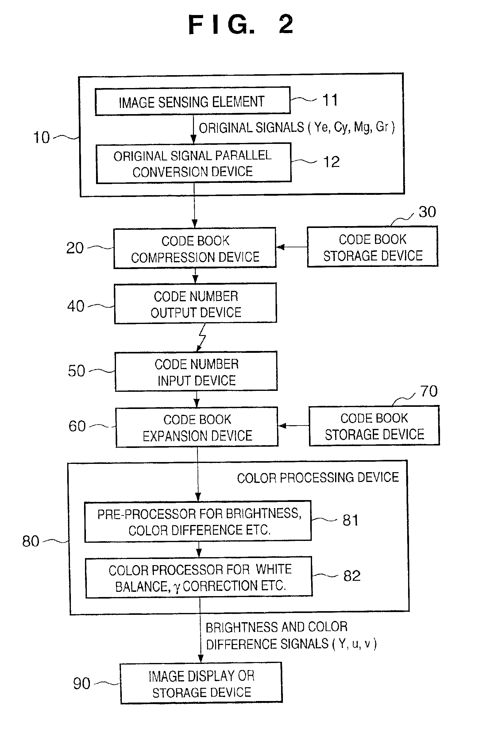
[0064]The second embodiment of the present invention will be described below with reference to FIG. 2. Note that the same reference numerals in this embodiment denote the same parts as those described in the first embodiment, and a detailed description thereof will be omitted.

[0065]In case of the second embodiment, the image sensing unit 10 includes an original signal parallel conversion device 12 to parallelly output serial original signals obtained from the image sensing unit 10. Since the original signals Ye, Cy, Mg, and Gr are parallelly output from the image sensing unit 10, in addition to the advantage attained by the first embodiment, pattern comparison in the code book compression device 20 can be performed in units of blocks each consisting of 4×4 pixels. Hence, high-speed pattern comparison can be attained, and the overall processing speed can be improved.

[0066]An image signal processing system according to the third embodiment of the present invention w...

fourth embodiment

(Fourth Embodiment)

[0071]The fourth embodiment of the present invention will be explained below with reference to FIG. 4. In the first to third embodiments, a case where compression based on the code book scheme is used as the information compression method is described. In this embodiment, a compression device 21 for performing DCT and quantization, variable length coding device 31, and output device 32 as information compression devices are provided to the image signal transmitting side. On the other hand, a variable length coding input device 41, and information expansion device 51 for performing reconstruction of information such as inverse quantization and inverse DCT processings are provided to the image signal receiving side.

[0072]In the image signal processing system with the aforementioned arrangement as well, the amount of information to be transmitted via a line can be greatly reduced, and high image quality can be obtained by minimizing deterioration of the image quality...


PUM


Abstract

An image signal processing method and system, which can greatly reduce the data size upon transmitting an image signal or storing the signal in a storage medium, and can obtain a high-quality image by preventing image quality after color processing from deteriorating. According to the method for processing an image signal output from an image sensing element, a compression step of compressing the image signal and an expansion step of expanding the compressed image signal are executed without executing color processing for executing at least white balance correction or correction, and the color processing is executed after completion of the compression and expansion steps, thereby preventing occurrence of block noise and high-frequency noise associated with compressing/expanding image data after the color processing of the image signal.

Description

BACKGROUND OF THE INVENTION[0001]This invention relates to an image signal processing method, image signal processing system, storage medium, and image sensing apparatus.[0002]An image signal processing system that processes color image signals executes predetermined color correction for original signals output from an image sensing element to generate a brightness signal and color difference signals, and displays an image represented by the brightness signal and color difference signals on an image display device or stores them in a storage medium.[0003]Various techniques for reducing the capacity of a storage medium required for storing image data or reducing the network load upon transmitting image data in such image signal processing system have been proposed.[0004]FIG. 10 is a block diagram showing an example of a conventional image signal processing system. As shown in FIG. 10, original signals (complementary original signals Ye, Cy, Mg, and Gr in this embodiment, but the same...

Claims


Application Information

Patent Timeline
IPC IPC(8): H04N1/64H04N1/60H04N9/64H04N1/41H04N5/225H04N9/04H04N9/69H04N9/73H04N9/804H04N9/808H04N11/04
CPCH04N1/60H04N1/64H04N9/643
Inventor OHMI, TADAHIROSUGAWA, SHIGETOSHIUENO, ISAMUOGAWA, KATSUHISAKOIZUMI, TORUKOCHI, TETSUNOBUSAKURAI, KATSUHITONAKAYAMA, TAKAHIROMORIMOTO, TATSUO
Owner OHMI
Why Eureka
Try Eureka