Monitoring camera system, imaging device, and video display device

Inactive Publication Date: 2009-10-15
PANASONIC CORP
View PDF12 Cites 42 Cited by
  • Summary
  • Abstract
  • Description
  • Claims
  • Application Information

AI Technical Summary

Benefits of technology

[0019]According to the monitoring camera system of the present invention, it is possible to designate a video display device with which a monitored video can be viewed in accordance with an object in the monitored v

Problems solved by technology

On the other hand, a widespread use of the mon

Method used


Image

  • Monitoring camera system, imaging device, and video display device
  • Monitoring camera system, imaging device, and video display device
  • Monitoring camera system, imaging device, and video display device

Examples


first embodiment

[0073](First Embodiment) The following describes the present invention with reference to the drawings.

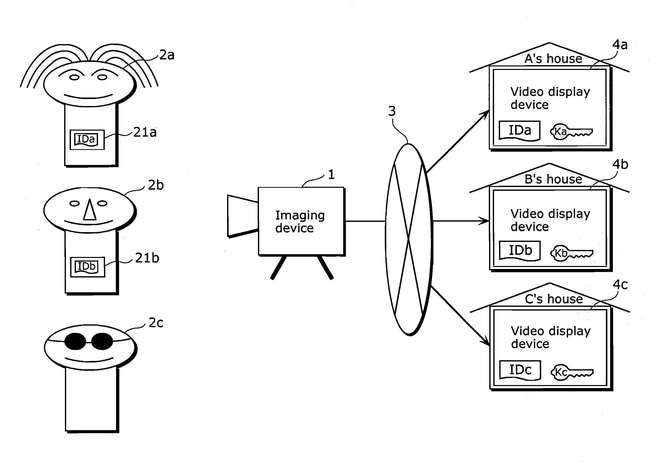
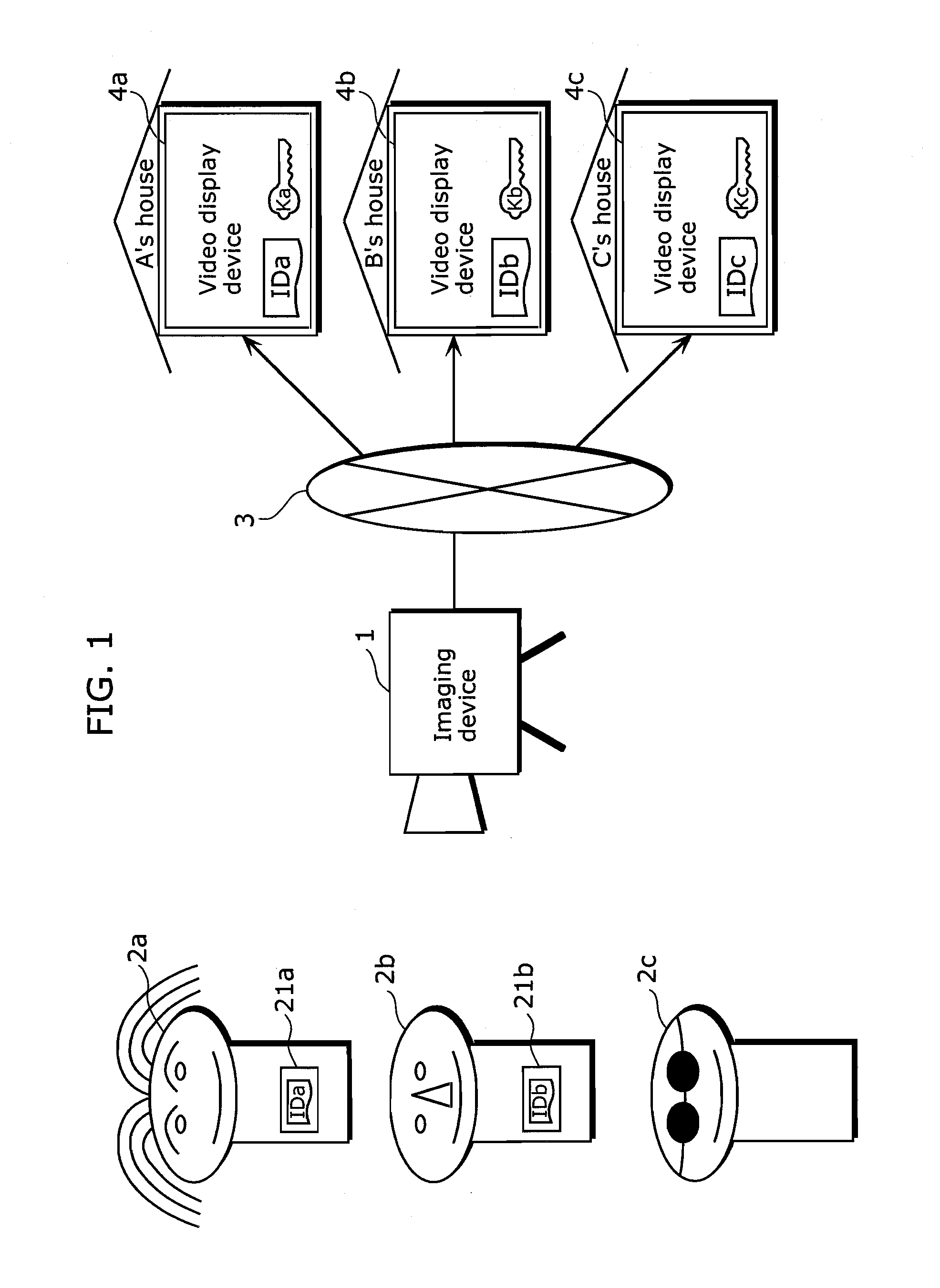
[0074](Summary of Monitoring Camera System) FIG. 1 is a block diagram showing a configuration of a monitoring camera system according to a first embodiment of the present invention. The monitoring camera system is a system in which privacy of a predetermined object is protected and the object is monitored, and includes an imaging device 1 and video display devices 4a, 4b, and 4c connected via a network 3.

[0075]Here, the imaging device 1 is assumed to capture objects 2a, 2b, and 2c. Moreover, it is assumed that the object 2a and the object 2b possess an identification (ID) tag 21a and an ID tag 21b respectively and that the object 2c does not possess an ID tag.

[0076]In the monitoring camera system, the imaging device 1 captures the objects 2a, 2b, and 2c. The imaging device 1 distributes captured video via the network 3 to the video display devices 4a, 4b, and 4c. The following descr...

second embodiment

[0186]Furthermore, in the imaging device 6 the face video separation unit 65 is designed to extract, from the digital video data to be outputted from the video processing unit 61, a partial image matching with the face image data corresponding to the video display device identifier received by the communication unit 62 as face video. However, a method of extracting the face video is not limited by the above-mentioned method and may not be a method using the video display device identifier. For example, an object included in the digital video data may be directly identified by searching the face image data pre-registered in the face image list storage unit 63 by the pattern matching among the digital video data.

[0187]In addition, although, in the first embodiment, a configuration is that the digital video data is encrypted using the content key, the content key used for encryption is encrypted by the device key, and the encrypted digital video data and the content key are distribute...


PUM


Abstract

An imaging device (1) for imaging a subject and distributing the captured video. The privacy of the subject is adequately protected, and a required monitoring function is realized. The imaging device (1) comprises an imaging section (10) for imaging a subject, an encryption key list storage section (13) storing encryption key data associated with a video display device and permitting display of the captured video showing the subject for each subject, a communication section (12) for judging whether or not a specific subject corresponding to the video display device is shown in the captured video, a video encrypting section (15) for encrypting a partial video of at least the specific subject in the captured video with encryption key data associated with video display device specifying information on the specific subject when the communication section (12) has judged that the specific subject is shown in the captured image, thereby to convert the partial video into an encrypted video, and create a limited captured video including the encrypted video, and a video transmitting section (16) for distributing the limited captured video to the video display device.

Description

TECHNICAL FIELD[0001]The present invention relates to a monitoring camera system with which privacy of an object is adequately ensured and monitoring by a monitoring camera is possible.BACKGROUND ART[0002]In recent years, a monitoring camera has been installed in an apartment, a house, and the like, so as to prevent a suspicious individual from intruding into a building. In addition, the monitoring camera is mainly installed at a street corner, in a park, and the like, of a new town, so that neighborhood residents can watch a monitored image inside. In this way, a parent, being at home, can check on a child playing in the park and the like so that the parent can let the child play outside without a fear.[0003]On the other hand, a widespread use of the monitoring camera may bring about a privacy issue. That is to say, people are subject to monitoring by the monitoring camera installed at various places in town or in the park. As a result, there is a chance that a third person may con...

Claims


Application Information

Patent Timeline
IPC IPC(8): H04N7/167G06F21/60G06F21/62H04L9/06H04L9/14H04N5/225H04N7/173H04N7/18H04N21/2347H04N21/4405
CPCH04N7/18H04N21/835H04N21/2347H04N21/2187
Inventor YOKOTA, KAORUOHMORI, MOTOJIWATANABE, KAZUHISASASO, ATSUSHISAKAKIBARA, MIZUHOYAMAMOTO, NAOAKI
Owner PANASONIC CORP
Why Eureka
Try Eureka