Vehicular power generation system and power generation control method for the same

a technology of power generation system and control method, which is applied in the control system, control system, electrical apparatus, etc., can solve the problems of low efficiency, large amount of work, and the amount of fuel to be consumed for power generation does not consider the efficiency of a generator, so as to reduce the amount of fuel consumption per electric energy of the internal combustion engine in operation, the effect of high power generation efficiency and small amount of fuel

Active Publication Date: 2013-11-21
MITSUBISHI ELECTRIC CORP
View PDF8 Cites 0 Cited by
  • Summary
  • Abstract
  • Description
  • Claims
  • Application Information

AI Technical Summary

Benefits of technology

[0013]According to a vehicular power generation system and a power generation control method for the vehicular power generation system of the present invention, a generator is made to operate at electric power with high power generation efficiency according to an operating point of the generator in an operating range of an internal combustion engine, the operating range being small in the amount of fuel to be consumed for power generation, whereby the amount of fuel consumption per electric energy of the internal combustion engine in operation can be reduced.
[0014]Furthermore, according to a vehicular

Problems solved by technology

However, in the prior art disclosed in Patent Document 1, the amount of fuel to be consumed for power generation does not consider efficiency of a generator (the ratio of electric power outputted by the generator to work that drives the generator) and driving time of the gener

Method used


Image

  • Vehicular power generation system and power generation control method for the same
  • Vehicular power generation system and power generation control method for the same
  • Vehicular power generation system and power generation control method for the same

Examples


embodiment 1

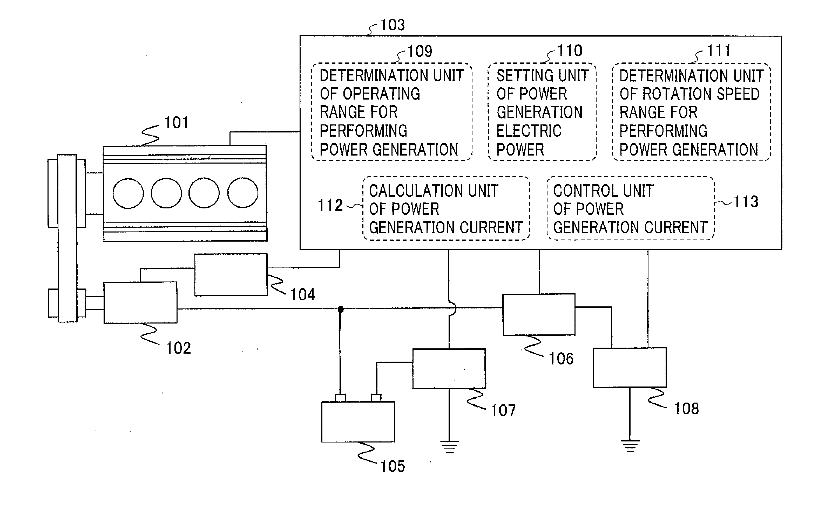
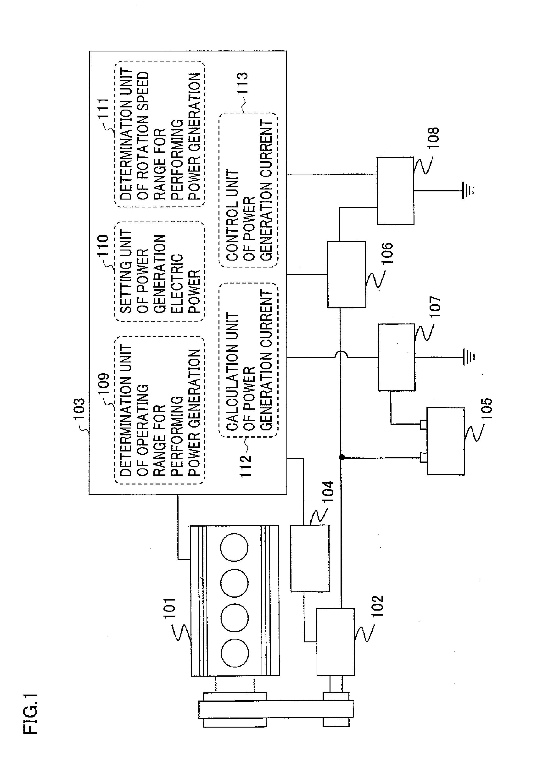
[0021]FIG. 1 is a schematic configuration diagram of an internal combustion engine in which a vehicular power generation system according to Embodiment 1 of the present invention is installed. In FIG. 1, an internal combustion engine 101 drives a generator 102 via a drive belt; and a power generation control device 103 controls power generation electric power of the generator 102 by operating regulating voltage of a power generation voltage regulating device 104. Incidentally, in this case, a configuration including the power generation voltage regulating device 104 is shown as a configuration with higher control accuracy. However, as an inexpensive system, the power generation control device 103 can include a unit that substitutes for the power generation voltage regulating device 104 inside thereof; and, in this case, the power generation control device 103 can directly control power generation electric power of the generator 102.

[0022]The electric power generated by the generator...


PUM


Abstract

A vehicular power generation system includes: a battery which is charged by power generation electric power of a generator that is driven by an internal combustion engine; and a power generation control device which reduces the amount of fuel to be consumed for power generation of the internal combustion engine. The power generation control device includes: a unit which sets an operating range that is small in the amount of fuel to be consumed for an increase in torque of the internal combustion engine; a unit which sets electric power with high power generation efficiency to a target value of power generation electric power according to rotation speed and power generation voltage of the generator; and a unit which controls so that the amount of power generation of the generator is a target value when the operating point of the internal combustion engine is in the operating range.

Description

BACKGROUND OF THE INVENTION[0001]1. Field of the Invention[0002]The present invention relates to vehicular power generation systems and power generation control methods for the same and, more particularly, relates to a reduction in the amount of fuel to be consumed for power generation of an internal combustion engine.[0003]2. Description of the Related Art[0004]Conventionally, a generator is installed on a vehicle to supply electric power for various types of electrical loads and to charge a battery. Since the generator is driven by an internal combustion engine to perform power generation, fuel is consumed also for the power generation while the internal combustion engine operates.[0005]On the other hand, in recent years, an improvement of fuel consumption of a vehicle is desired because of environmental problem and a method for reducing the amount of fuel to be consumed for power generation is proposed (for example, see Patent Document 1).[0006]This prior art is configured to red...

Claims


Application Information

Patent Timeline
IPC IPC(8): H02P9/04
CPCH02P9/48H02P9/008H02P2101/45
Inventor TANI, HIDEAKIDATE, TOSHIAKIWACHI, SATOSHI
Owner MITSUBISHI ELECTRIC CORP
Why Eureka
Try Eureka