
Method for reducing air flow in an engine at idle

a technology of engine air flow and engine idle, which is applied in the direction of electric control, combustion-air/fuel-air treatment, machines/engines, etc., can solve the problems that the passive devices in the engine system may also affect the engine air flow during idle, and the fuel quantity may be additionally diminished during idle, so as to achieve the effect of reducing the amount of fuel, and increasing efficiency

Active Publication Date: 2017-05-23
FORD GLOBAL TECH LLC
View PDF80 Cites 0 Cited by
  • Summary
  • Abstract
  • Description
  • Claims
  • Application Information

AI Technical Summary

Benefits of technology

[0002]Engine systems in vehicles may be designed to utilize smaller amounts of fuel during idle conditions. These smaller amounts of fuel may be further reduced by prudently managing electrical loads during idle as well as by using alternators with higher efficiency. Further still, by generating electrical power from regenerative braking instead of combusting fuel for operating an engine-driven electrical generator, fuel quantities may be additionally diminished during idling.
[0004]The inventors herein have recognized the above issue and identified an approach to at least partly address the issue. In one example, a method for a boosted engine comprises adjusting, via an electronic controller, an opening of a common shut-off valve (CSOV) based on engine idling conditions, and each of a motive flow through an aspirator and a crankcase ventilation flow from a crankcase, the motive flow and the crankcase ventilation flow combined together and flowing through the CSOV when the CSOV is open. In this way, air flow from passive devices such as the CV valve and the aspirator can be significantly reduced during engine idle.
[0006]In this way, engine air ingestion during idle conditions may be reduced. Specifically, air ingestion from passive devices such as a CV valve and / or an aspirator may be substantially decreased during engine idling allowing a significant decrease in a rate of fuel consumption. By employing a common shut-off valve to regulate both air flow received from the aspirator and blow-by gases from the CV valve, a simpler control algorithm for the shut-off valve may be deployed. A serendipitous benefit of using the common shut-off valve may include utilizing aspirators with higher motive flow rates for increased vacuum generation. Further, the presence of the CSOV may also enable an increase in the size of a low flow orifice in the CV valve. By increasing the size of the low flow orifice, a higher evacuation rate of blow-by gases may be achieved when the common shut-off valve is open and manifold vacuum is deeper. Overall, engine performance may be improved while lowering operational costs due to the reduction in fuel consumption.

Problems solved by technology

Further still, by generating electrical power from regenerative braking instead of combusting fuel for operating an engine-driven electrical generator, fuel quantities may be additionally diminished during idling.
However, passive devices in the engine system may also affect engine air flow during idle.

Method used


Image

  • Method for reducing air flow in an engine at idle
  • Method for reducing air flow in an engine at idle
  • Method for reducing air flow in an engine at idle

Examples


Embodiment Construction

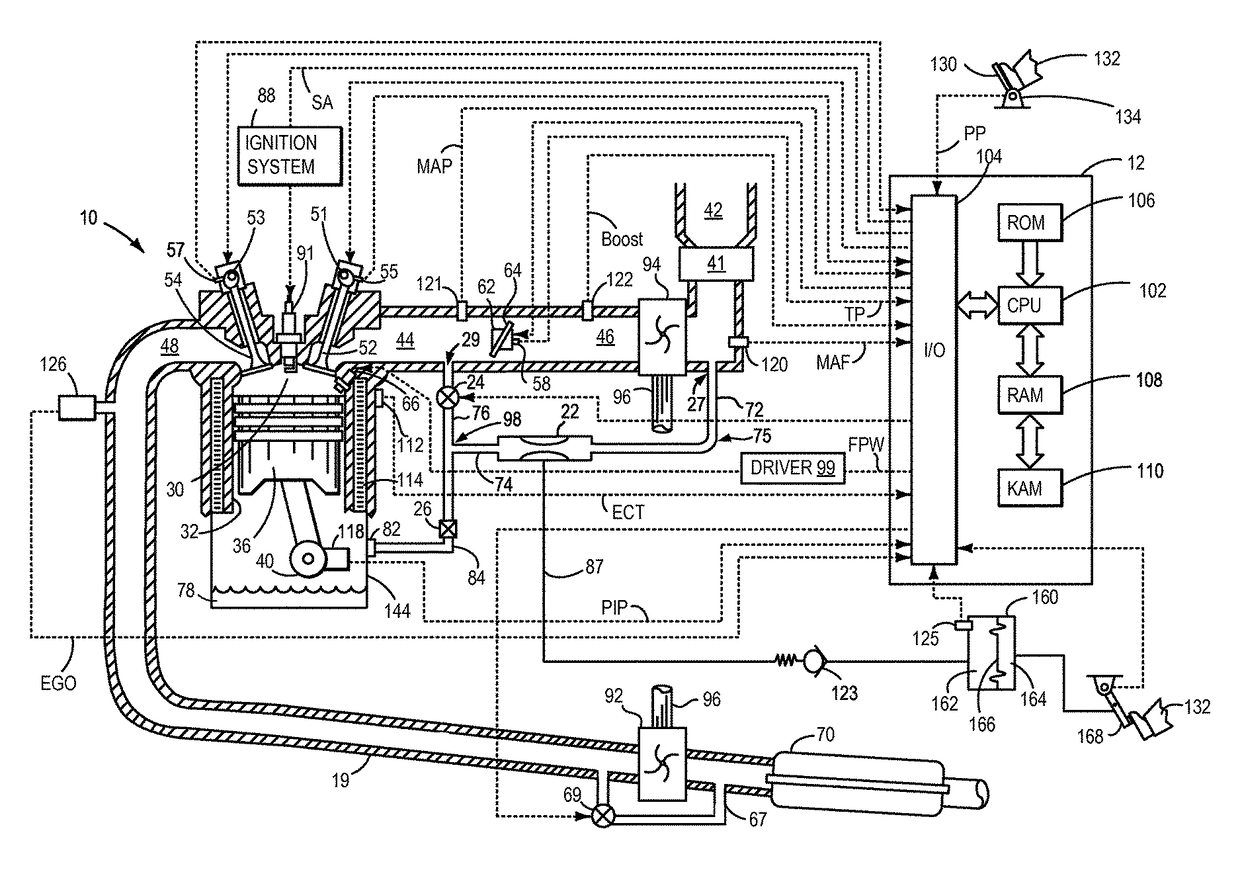
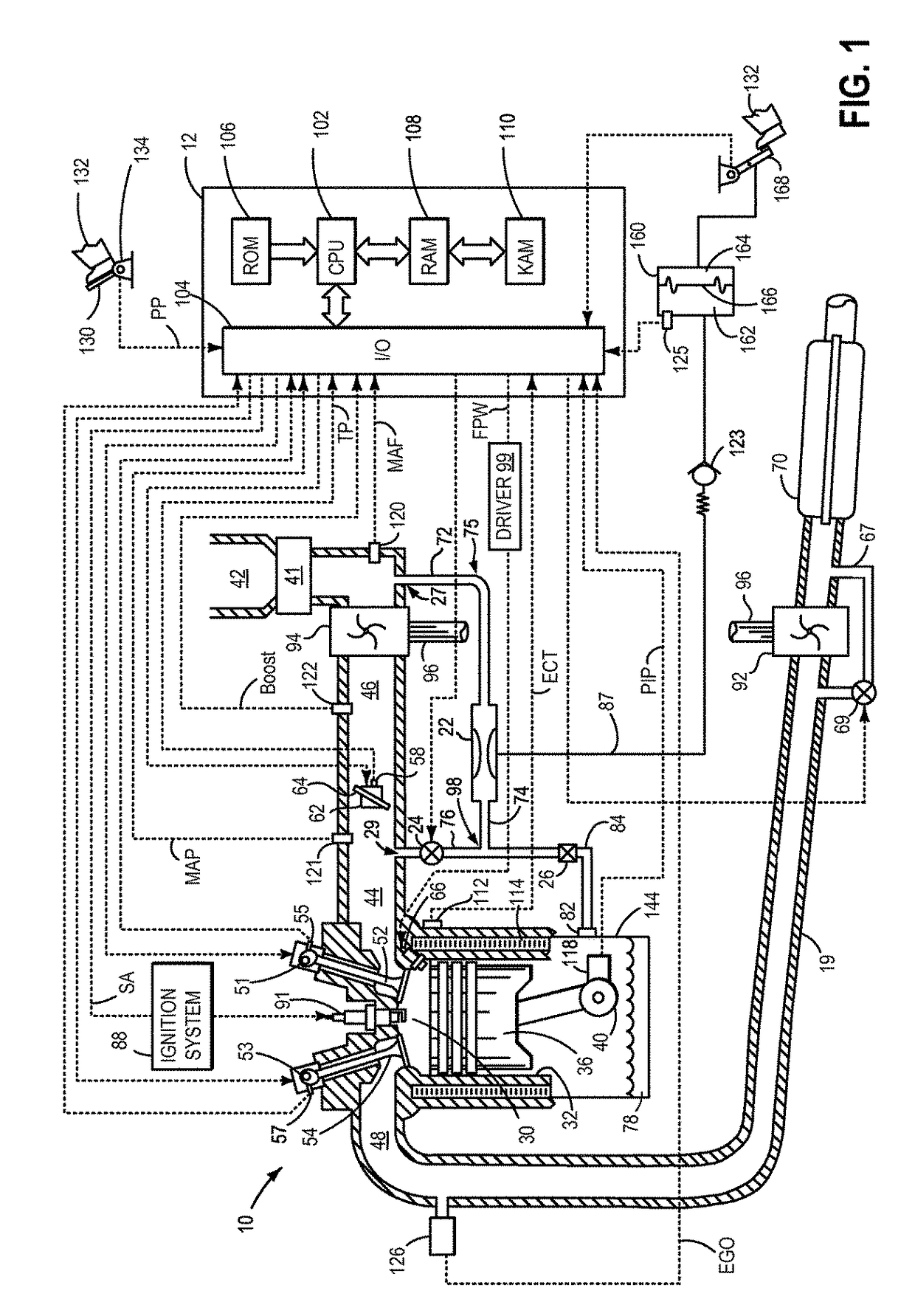
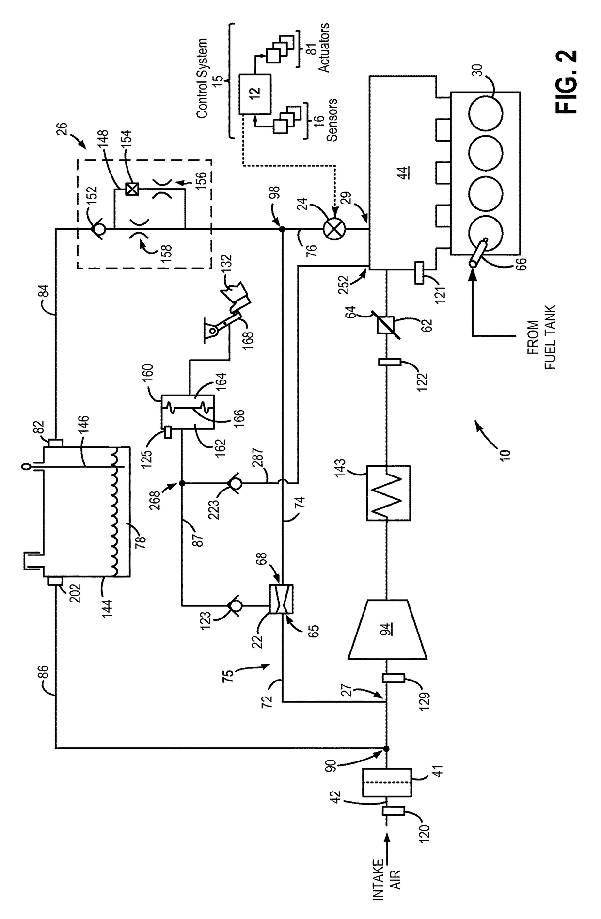
[0016]The following description relates to systems and methods for reducing air flow in a boosted engine system, such as the engine system of FIGS. 1 and 2, during idle conditions. The engine system may ingest air from distinct sources (other than intake air flow) such as from a vacuum generating aspirator, a crankcase, a fuel vapor canister, etc. A common shut-off valve (CSOV) may be included in a common channel, the CSOV capable of regulating flow through each of the common channel, the aspirator, and a crankcase ventilation (CV) valve. The common channel may stream air flow from each of an aspirator and from the CV valve into an intake manifold of the boosted engine system, based on engine conditions. The CSOV may be adjusted by a controller to a fully closed position in response to idling conditions in the boosted engine system (FIG. 6) and air flow through the aspirator may be ceased along with CV flow. When the engine is not idling and pressure in the intake manifold is lower ...


PUM


Abstract

Methods and systems are provided for controlling air ingestion in an engine during idle conditions. One example approach includes adjusting an opening of a common shut-off valve via an electronic controller, the common shut-off valve regulating each of motive flow through an aspirator and crankcase ventilation (CV) flow from a crankcase. As such, the common shut-off valve may be closed by the electronic controller during engine idle to cease each of the motive flow through the aspirator and the CV flow from the crankcase.

Description

FIELD[0001]The present application relates to methods for controlling air flow in an internal combustion engine during engine idle.BACKGROUND AND SUMMARY[0002]Engine systems in vehicles may be designed to utilize smaller amounts of fuel during idle conditions. These smaller amounts of fuel may be further reduced by prudently managing electrical loads during idle as well as by using alternators with higher efficiency. Further still, by generating electrical power from regenerative braking instead of combusting fuel for operating an engine-driven electrical generator, fuel quantities may be additionally diminished during idling.[0003]As fuel consumption during idle is reduced, a corresponding decrease in intake air flow may be desired. As such, intake air flow during idle may be actively regulated via an electronic throttle in an engine intake. However, passive devices in the engine system may also affect engine air flow during idle. For example, vehicle systems may include one or mor...

Claims


Application Information

Patent Timeline
Patent Type & Authority Patents(United States)
IPC IPC(8): F02D41/08F02D41/00F02D41/22F02M35/10F02B33/00F01M13/00F02M35/104
CPCF02D41/0007F01M13/0011F02B33/00F02D41/08F02D41/221F02M35/10222F02M35/10229F02D41/0025F02D2250/41F02M35/104Y02T10/144Y02T10/40F02D9/00F01M13/022F01M13/023Y02T10/12
Inventor PURSIFULL, ROSS DYKSTRALUEHRSEN, ERIC
Owner FORD GLOBAL TECH LLC
Learn More