Method and apparatus for the start-up and control of pulse combustors using selective injector operation

a technology of selective injector operation and pulse combustors, which is applied in the direction of electrical control, combustion types, lighting and heating apparatus, etc., can solve the problem of small overall amount of fuel supplied to the pulsejet engine, and achieve the effect of reducing the likelihood of engine operation shutdown and increasing efficiency and stability in engine operation

Active Publication Date: 2021-04-15
NORTH AMERICAN WAVE ENGINE CORP
View PDF0 Cites 4 Cited by
  • Summary
  • Abstract
  • Description
  • Claims
  • Application Information

AI Technical Summary

Benefits of technology

[0014]The present invention is directed to pulsejet engines that have a novel Electronic Fuel Injection (“EFI”) system that includes one or more electrically controlled fuel injectors that can be selectively operated for start-up and controlling such pulsejet engines. The rate and / or pattern of fuel delivery to pulsejet engines according to the present invention can be varied not only by controlling the amount of time the injectors are open versus closed to define a “duty cycle,” but also with the capability to selectively disable one or more fuel injectors in the programmed manner for start-up and control of pulsejet engines. This capability to selectively disable one or more injectors provides a novel method by which the engine controller under operator control can control the pulsej et engine over a wider throttle range, provide increased efficiency and stability in engine operation, and reduce the likelihood of engine operation shutdown due to injection timing inaccuracies or physical cycle-to-cycle variation.
[0015]The present invention contemplates a system and method for improved pulsejet engine start-up by selectively disabling one or more fuel injectors, so that during engine start-up, the fewest number of fuel injectors need to be held open / on for as long as practically with the maximum time being for the full length of the engine cycle. This will dramatically increase the likelihood fuel will be available to the engine during the initial air inflow event during the start-up process. This will also result in a smaller overall amount of fuel being supplied to the pulsejet engine than would be the case if all of the injectors were operational. Therefore, implementation of the present invention will result in a much higher likelihood of a successful engine start-up and operational stability under low-throttle conditions. Fuel injector selectivity can also be used during normal engine operation for more efficient and sustained engine operation.

Problems solved by technology

This will also result in a smaller overall amount of fuel being supplied to the pulsejet engine than would be the case if all of the injectors were operational.

Method used


Image

  • Method and apparatus for the start-up and control of pulse combustors using selective injector operation
  • Method and apparatus for the start-up and control of pulse combustors using selective injector operation
  • Method and apparatus for the start-up and control of pulse combustors using selective injector operation

Examples


Embodiment Construction

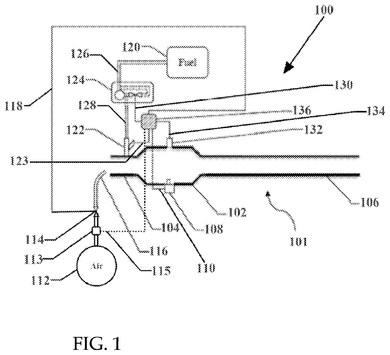
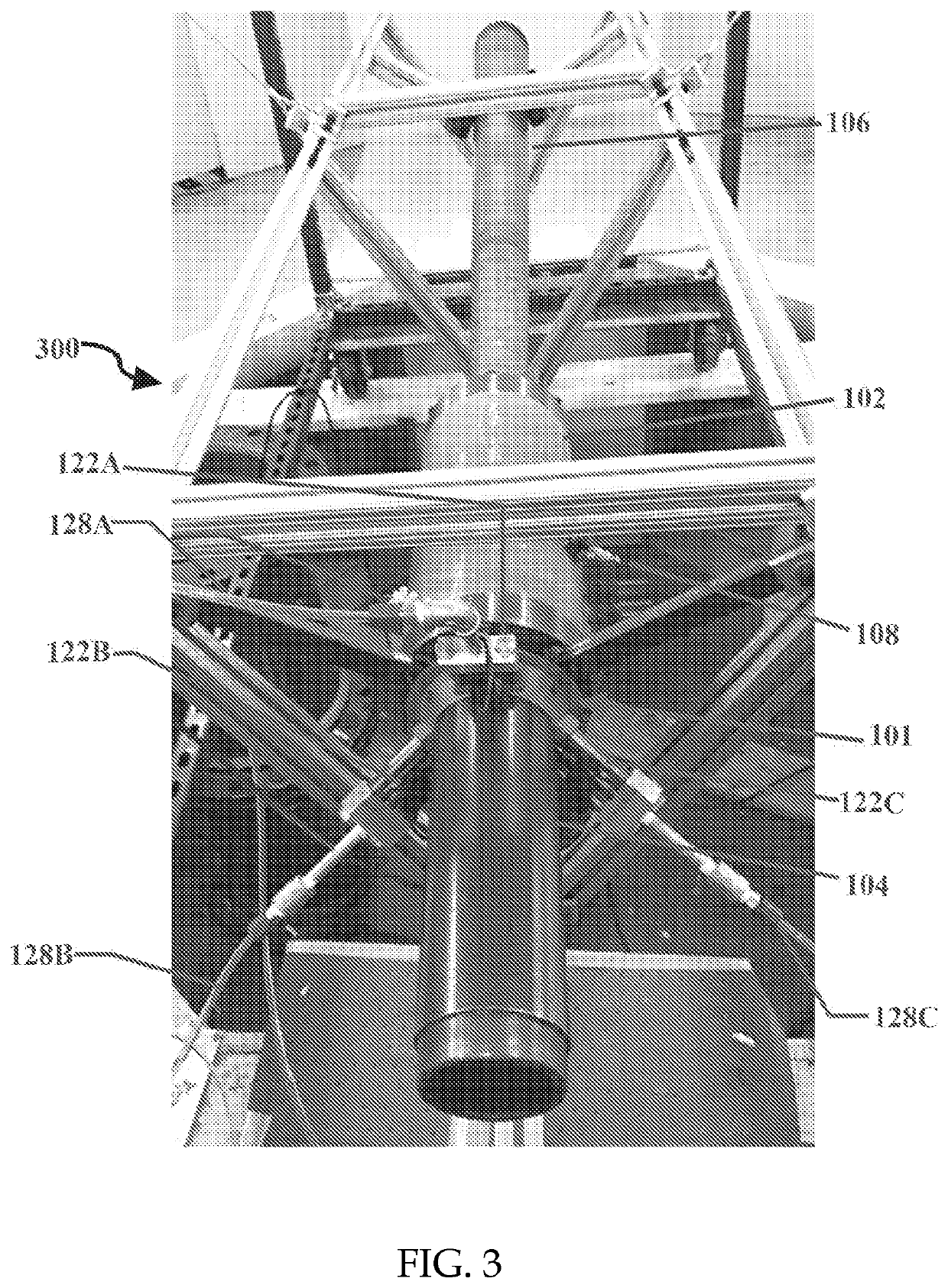
[0026]FIG. 1, generally at 100, shows a representative schematic drawing of an embodiment of the present invention for start-up and control of pulse combustors. In FIG. 1, pulse combustor 101 preferably includes inlet pipe 104 that connects to combustion chamber 102. Combustion chamber 102 also connects to exhaust pipe 106. The pulse combustor also includes one or more fuel injector(s) 122 of which only one is shown in FIG. 1. A better view of multiple injectors being associated with a pulse combustor is shown at FIG. 3, which will be described in detail later in the specification. When multiple injectors are used, they are located around inlet pipe 104 or combustion chamber 102. In each case, the fuel injectors point inwardly toward the interior of the structure on which they are disposed. However, a person of ordinary skill in the art would understand that the multiple fuel injectors, their locations, quantities, and geometries may be varied and still be within the scope of the pr...


PUM


Abstract

A system and method is disclosed for the start-up and control of pulsejet engines and this system includes an Electronic Fuel Injection (“EFI”) system that further includes one or more electrically controlled fuel injectors that can be selectively operated for start-up and control of such pulsejet engines. According to the system and method, the rate and / or pattern of fuel delivery to pulsejet engines can be varied not only by controlling the amount of time the fuel injectors are open versus closed to define a “duty cycle,” but also with the capability to selectively disable one or more fuel injectors in the programmed manner for start-up and control of such pulsejet engines.

Description

CROSS-REFERENCES TO RELATED APPLICATIONS[0001]This Application claims the benefit under 35 U.S.C. 119(e) to U.S. Provisional Patent Application No. 62 / 658,989, filed Apr. 17, 2018, and U.S. Provisional Patent Application No. 62 / 725,117, filed Aug. 30, 2018, the entirety of each is explicitly incorporated by reference herein.[0002]All publications, patent applications, patents, or other references mentioned herein are incorporated by reference in their entirety. The patent and scientific literature referred to herein establishes knowledge that is available to those skilled in the art. The issued patents, applications, and other publications that are cited herein are hereby incorporated by reference to the same extent as if each was specifically and individually indicated to be incorporated by reference. In the case of inconsistencies, the present disclosure will prevail.FIELD OF THE INVENTION[0003]The present invention relates to combustors and jet engines. More specifically, the pre...

Claims


Application Information

Patent Timeline
Patent Type & Authority Applications(United States)
IPC IPC(8): F02D41/40F02D41/38
CPCF02D41/402F23R7/00F02D41/3845F02C5/10F23C2205/10F23N1/002F02C9/48F05D2270/301F02K7/067
Inventor MAQBOOL, DAANISHRAVIN, NITAYMYERS, CARSON
Owner NORTH AMERICAN WAVE ENGINE CORP
Why Eureka
Try Eureka