Light receiver, optical communication system and method

a technology of optical communication system and light receiver, applied in the field of light receiver, optical communication system and method, can solve the problems of reducing communication quality, affecting the operation of delay interferometer, and suffering from a large amount of noise, so as to reduce the operating frequency of delay interferometer, eliminate the instabilities caused by an adjustment mechanism, and demodulate the dpsk signal

a technology of optical communication system and light receiver, applied in the field of light receiver, optical communication system and method, can solve the problems of reducing communication quality, affecting the operation of delay interferometer, and suffering from a large amount of noise, so as to reduce the operating frequency of delay interferometer, eliminate the instabilities caused by an adjustment mechanism, and demodulate the dpsk signal

US8320779B2Active Publication Date: 2012-11-27NEC CORP

Image

  • Light receiver, optical communication system and method
  • Light receiver, optical communication system and method
  • Light receiver, optical communication system and method

Examples


1st exemplary embodiment

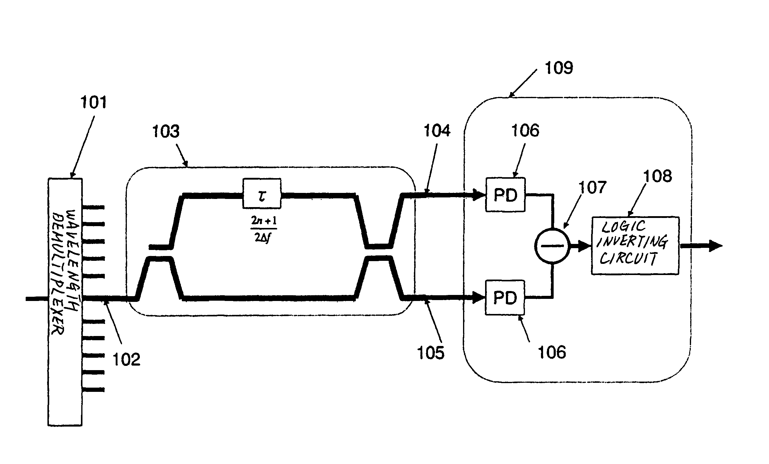
[0076]FIG. 5 is a block diagram showing a configuration of a receiver according to a first exemplary embodiment of the present invention.

[0077]As shown in FIG. 5, the receiver according to the first exemplary embodiment comprises wavelength demultiplexer 101, delay interferometer 103, and light receiver 109. Light receiver 109 comprises light detectors 106, subtractor 107, and logic inverting circuit 108.

[0078]In FIG. 5, for the sake of brevity, delay interferometer 103 and light receiver 109 are connected to an output terminal of wavelength demultiplexer 101. Actually, the receiver has a plurality of delay interferometers 103 and a plurality of light receivers 109, which are connected to respective output terminals of wavelength demultiplexer 101. Delay interferometers 103 and light receivers 109 do not need to be connected to all the output terminals of wavelength demultiplexer 101. Rather, delay interferometers 103 and light receivers 109 may be connected to only output terminals...


PUM


Abstract

A receiver includes wavelength demultiplexer for demultiplexing a received WDM light into light signals at respective central frequencies thereof, delay interferometer for converting a light signal output from wavelength demultiplexer into an intensity signal, and light detector for converting an output signal from delay interferometer into an electric signal. The interval between interferential frequencies of delay interferometer is 2 / (2n+1) times the interval between the central frequencies of the WDM light. Logic inverting circuit outputs the output signal from the light detector while non-inverting or inverting the logic level thereof depending on the received central frequency.

Description

[0001]This application is the National Phase of PCT / JP2006 / 319880, filed Oct. 4, 2006, which claims priority to Japanese Application No. 2005-291832, filed Oct. 5, 2005, the disclosures of which are hereby incorporated by reference in their entirety.TECHNICAL FIELD[0002]The present invention relates to a receiver for receiving a phase-modulated light signal, an optical communication system incorporating such a receiver, and an optical communication method.BACKGROUND ART[0003]Optical communication systems employing optical fibers are an important technology for transmitting a large amount of data over a long distance. Optical communication systems that are currently in use are of the intensity modulation type. The intensity modulation process is a modulation process for assigning the “presence” and “absence” of optical pulses to “1” and “0” of digital signals. The intensity modulation process is widely used in a wide range of applications because it is easy to generate and detect mod...

Claims


Application Information

Patent Timeline
27 Nov 2012
Publication
US8320779B2
IPC
H04B10/06; H04B10/516; H04B10/556; H04B10/58; H04B10/61; H04J14/00; H04J14/02
CPC
H04B10/66
Inventors
FUKUCHI, KIYOSHI; ITO, TOSHIHARU