Power unit

a power unit and power technology, applied in mechanical equipment, transportation and packaging, gearing, etc., can solve the problems of reducing the manufacturing cost of the vehicle, inhibiting the reduction of weight or downsizing, and auxiliary devices not being able to drive by the engine, so as to simplify the configuration of the first power transmission path

Active Publication Date: 2012-12-11
HONDA MOTOR CO LTD
View PDF12 Cites 9 Cited by
  • Summary
  • Abstract
  • Description
  • Claims
  • Application Information

AI Technical Summary

Benefits of technology

[0019]According to the third invention, it is possible to maintain the rotation direction of the first carrier to be one of the forward and reverse rotation directions in various driving states of the driven unit by appropriately setting the reduction ratio of the first power transmission path and the gear ratios of the first ring gear and the first sun gear of the first planetary gear unit. Therefore, in various driving states of the driven unit, it is possible to maintain the direction of the power transmitted from the first carrier to the auxiliary device to be a direction appropriate for driving the auxiliary device. Consequently, it is possible to provide situations enabling the auxiliary device to be driven as many as possible.
[0024]According to the fifth invention, in the state where the first power transmission system is placed in the first operating state and the second power transmission system is placed in the fourth operating state, even if the rotation direction of the third rotating element of the differential gear is limited to one direction, it is possible to change the direction of the power transmitted from the output shaft of the prime mover to the driven unit via the differential gear and the first power transmission path by switching the operating state of the forward / reverse rotation switching mechanism between the seventh operating state and the eighth operating state. Therefore, the driven unit is able to be driven in either of the forward and reverse rotation directions. Moreover, for example, in the case where the fifth invention is combined with the fourth invention, the third rotating element and the second rotating element of the differential gear are able to be rotated in the same direction even if the driven unit is driven in either of the forward and reverse rotation directions only with the power of the rotary actuator. Therefore, even if the driven unit is driven in either of the forward and reverse rotation directions, the auxiliary device is able to be driven by transmitting a part of the power of the rotary actuator. Moreover, the rotation direction of the third rotating element of the differential gear is able to be limited to one direction, thereby preventing the operation mode of the power unit of the present invention from being complicated.
[0032]In this manner, the forward / reverse rotation switching mechanism is provided with the function of the first power transmission system, thereby enabling a reduction in the number of parts of the components of the first power transmission path to simplify the configuration of the first power transmission path.
[0037]The provision of the function of the second locking mechanism to the forward / reverse rotation switching mechanism enables a reduction in the number of parts of the components of the first power transmission path to simplify the configuration of the first power transmission path.

Problems solved by technology

During the stop of engine operation, however, the auxiliary devices are not able to be driven by the engine.
Therefore, the technique has a problem of inhibiting a reduction in weight or downsizing and a decrease in manufacturing cost of the vehicle.

Method used


Image

  • Power unit
  • Power unit
  • Power unit

Examples


first embodiment

[0058]A first embodiment of the present invention will be described with reference to FIGS. 1 to 11.

[0059]First, referring to FIGS. 1 and 2, the configuration of a power unit 1 according to this embodiment will be described.

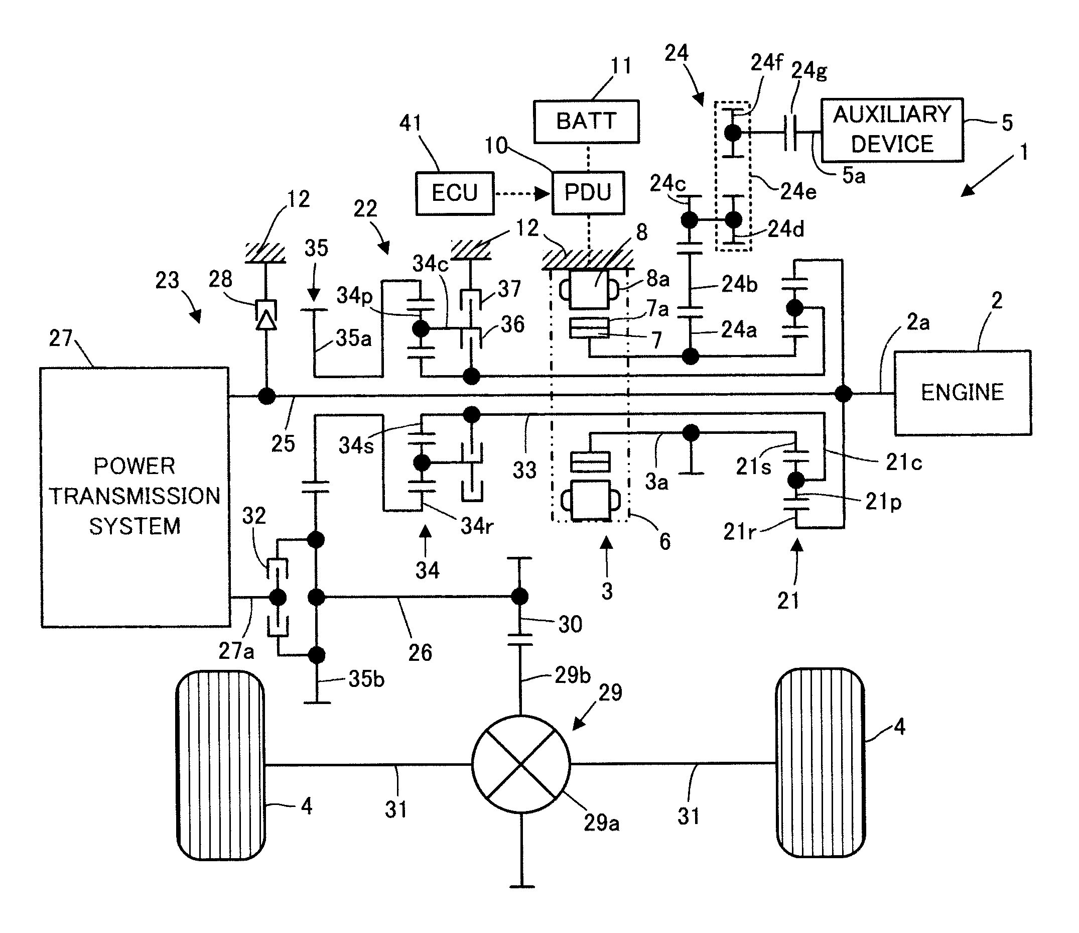
[0060]Referring to FIG. 1, the power unit 1 according to this embodiment is a power unit mounted on a hybrid vehicle, having an engine 2 and a motor 3 as power generation sources. Further, the power unit 1 is adapted to be capable of driving a pair of driving wheels 4, 4 by transmitting power of the engine 2 or the motor 3 to the driving wheels 4, 4. In addition, the power unit 1 is adapted to be capable of driving an auxiliary device 5 mounted on the vehicle by transmitting the power of the engine 2 or the motor 3 to the auxiliary device 5 as well as the driving wheels 4, 4. The auxiliary device 5 is, for example, an air conditioner compressor, a water pump, an oil pump, or the like.

[0061]In this embodiment, the engine 2 and the motor 3 correspond to a prime mov...

second embodiment

[0185]The following describes a second embodiment of the present invention with reference to FIGS. 12 to 20. First, the configuration of a power unit 51 according to this embodiment will be described with reference to FIG. 12. The power unit 51 according to this embodiment is different from the power unit 1 according to the first embodiment only in a part of the configuration. Therefore, in the description of the configuration of the power unit 51 according to this embodiment, the same components as in the first embodiment are denoted by the same reference numerals as in the first embodiment and their description will be omitted.

[0186]Referring to FIG. 12, the configuration of the power unit 51 according to this embodiment differs from that of the power unit 1 according to the first embodiment only in the parts related to the connection between the rotating elements of the first planetary gear unit 21 and the auxiliary device 5. Specifically, in the power unit 51 according to this e...


PUM


Abstract

A power unit includes: a differential gear (21) in which a first rotating element (21r) is connected to an output shaft of a prime mover (2), a second rotating element (21s) is connected to a body of rotation of a rotary actuator (3), and a third rotating element (21c) is connected to a driven unit (4) via a first power transmission path (22); a first power transmission system (34, 36, 37) selectively operable between an operating state for enabling power transmission in the first power transmission path (22) and an operating state for disconnecting the power transmission; a second power transmission path (23) connecting between the output shaft of the prime mover (2) and the driven unit (4); and a second power transmission system (32) selectively operable between an operating state for enabling power transmission in the second power transmission path and an operating state for disconnecting the power transmission, wherein an auxiliary device (5) is connected to one of the second rotating element (21s) and the third rotating element (21c) of the differential gear (21).

Description

BACKGROUND OF THE INVENTION[0001]1. Field of the Invention[0002]The present invention relates to a power unit for driving a driven unit such as wheels of a vehicle.[0003]2. Description of the Related Art[0004]For example, as a vehicle, which runs by transmitting engine power to driving wheels as a driven unit, there has conventionally been known a vehicle which automatically stops engine operation during a stop at an intersection (so-called an idle-stop vehicle) as described in Japanese Patent Application Laid-Open No. 2003-269212 (hereinafter, referred to as Patent Document 1).[0005]On the other hand, a vehicle generally includes various auxiliary devices such as a water pump, an air conditioner compressor, and a power steering pump. In this case, these auxiliary devices are able to be driven by using the engine power during engine operation. During the stop of engine operation, however, the auxiliary devices are not able to be driven by the engine.[0006]Therefore, in the case of t...

Claims


Application Information

Patent Timeline
Patent Type & Authority Patents(United States)
IPC IPC(8): F16H3/72
CPCB60K6/365B60K6/48B60K6/547B60W10/06B60W10/08B60W10/115B60W20/00B60L2240/421B60W2710/081F16H37/027Y02T10/6221Y02T10/6286Y02T10/642Y02T10/62Y02T10/64B60K2006/268B60W20/30
Inventor AKUTSU, SHIGEMITSUABE, NORIYUKI
Owner HONDA MOTOR CO LTD
Why Eureka
Try Eureka