Safety device

a safety device and sleeve technology, applied in the direction of flexible wall reciprocating engines, fastening means, sleeve/socket joints, etc., can solve the problems of releasing the clamping force, causing considerable harm to equipment and humans, and resetting the weight in motion. to achieve the effect of reliable protection

Inactive Publication Date: 2011-01-04
HOFMANN KLAUS
View PDF23 Cites 7 Cited by
  • Summary
  • Abstract
  • Description
  • Claims
  • Application Information

AI Technical Summary

Benefits of technology

[0008]As a result of the arrangement of such a valve, it becomes possible to couple the vertical movement or position of the weight with an actuation of the valve, and thus to provide an additional control for the pressure admission into the chamber or the clamping force resulting therefrom.
[0017]In an advantageous embodiment of the invention, the actuation element is arranged on a weight body, or on a part thereof, which weight body is guided in the Z direction. By means of this simplification of the construction, a direct connection is established between the vertical position of the weight and the opening or closing of the valve. Thus, a movement of the weight in the Z direction opens or closes the valve. By an appropriate selection of the clamp elements (for example, such that a clamping force is applied when the chambers have no pressure), one can advantageously achieve that a clamping force is never applied if the weight body has opened the valve as a result of its movement and thus released the pressure from the medium supply line so that it is pressureless.
[0021]An additional downward movement of the weight body relative to the base body should be prevented by the above-mentioned coupling. It is conceivable here to use a simple guide rod system, which, while allowing the movement by shifting of the weight body to a selectable extent relative to the base body, maintains the weight body in the vertical or Z direction at a predetermined separation from the base body by means of appropriate coupling to this base body.
[0026]In an additional advantageous embodiment, the valve is designed such that, in the opened position, it allows the medium to flow from the medium supply line into the environment. This is particularly advantageous when compressed air is admitted because the construction costs are then very low. By simply opening the supply line to the environment during the opening of the valve, the pressure in the supply line and thus also in the chamber of the clamping system is released.
[0027]In a similar embodiment, on the other hand, the valve is designed so that the medium is recycled in a medium recycling line provided particularly for that purpose, when the valve is opened. This can be required particularly if the chamber of the clamping system is operated with hydraulic oil or a similar fluid. Because the hydraulic oil cannot be released into the environment, recycling of the hydraulic oil through an appropriate line is made possible. Again, it is essential for the functioning of this valve that the valve, in the opened state, prevent the pressurization of the chamber of the clamping system, so that the pressure in the chamber is released, thus allowing a clamping effect to be built up.
[0036]However, an abutment provided between the component, which is fixed and functions as actuation element, and the base body catches the base body and the rod clamped to it in such a manner that the rod cannot be moved farther down over the abutment. Thus, the rod is reliably protected from an uncontrolled and possibly dangerous lowering.

Problems solved by technology

However, the disadvantage of the designs known from the state of the art is that, following a failure as described above, the connection of the corresponding medium results in the clamping force being released again, and the weight being again set in motion as a result of gravity.
This can cause considerable harm, both to equipment and to humans, if the connection of the medium occurs without sufficient consideration or safety provisions for the possible subsequent movement of the weight.
The safety mechanism thus works only to the extent that a failure of the system pressure stops a relative movement.
The consequences of reestablishing the system pressure are the responsibility of only the operating personnel and are thus associated with risk.

Method used


Image

  • Safety device
  • Safety device
  • Safety device

Examples


Embodiment Construction

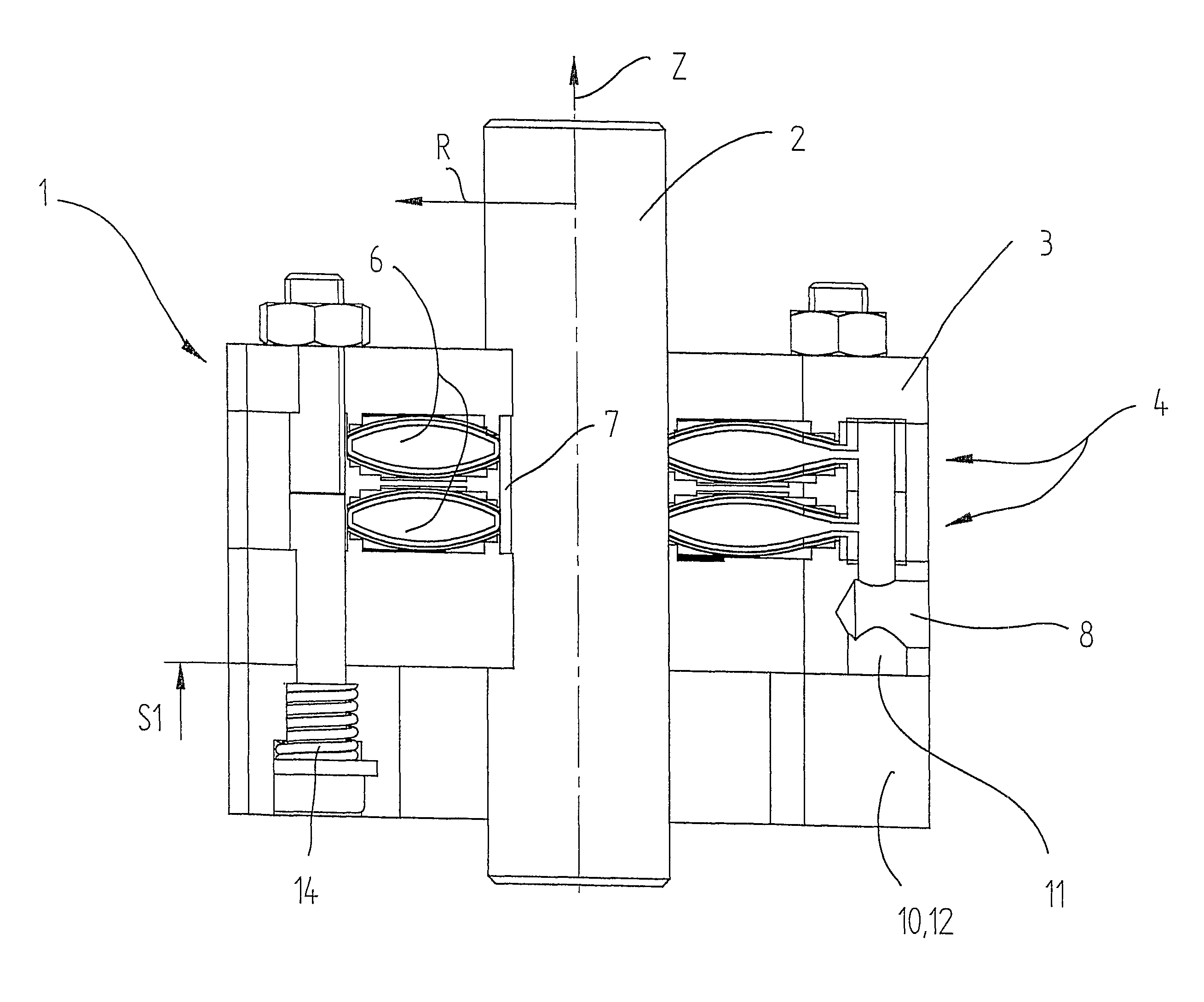
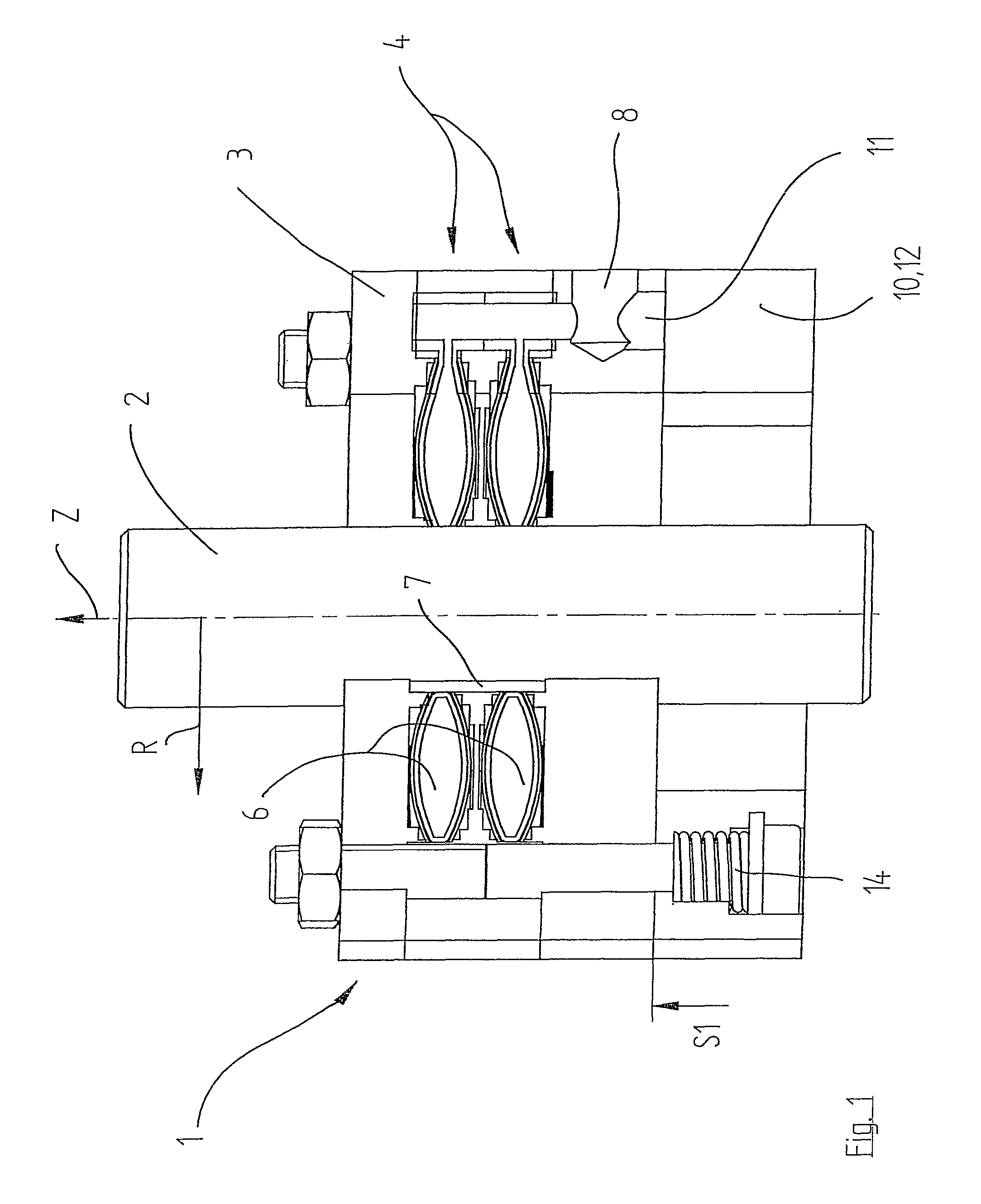
[0049]As can be seen in FIG. 1, a safety device 1 is provided. The safety device 1 surrounds a component 2 that, in the figures, is located substantially in the center of the image and arranged vertically. The component 2 is designed as a fixed guide in the form of a rod along which a base body 3 can slide up and down in a vertical direction Z.

[0050]A weight body 12 is mounted below the base body 3 by means of a screw system and a spring element 14 so that the weight body 12 is pressed in a detachable manner against the bottom side of the base body 3. Together with the base body 3, the weight body 12 is driven in an up and down movement by means of a lifting device that is not shown.

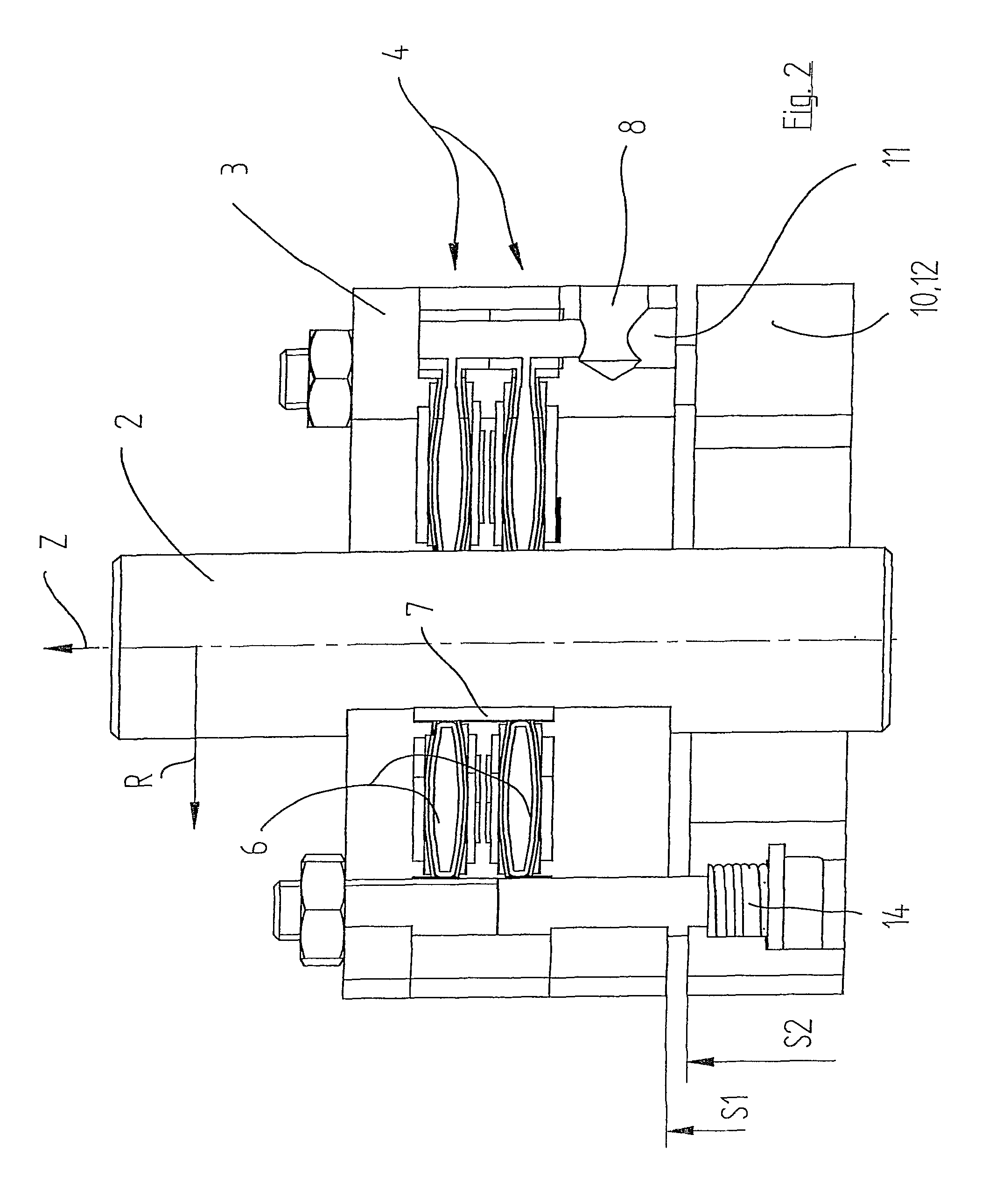
[0051]Inside the base body 3, two clamping systems 4, arranged one above the other, are provided. Each clamping system 4 presents, among other features, at least one elastically deformable chamber 6. In the case of elastic deformation of the chamber 6, its dimension in the radial direction changes so tha...


PUM


Abstract

A safety device is provided having a clamping system that uses pressure admission into a chamber of a clamp element dependent on the position of a weight to be carried relative to the clamping system. For this purpose a valve is provided in a medium supply line, which valve is to be opened or closed by means of a movable actuation element. Here, the actuation element should be movable in the same direction in which the weight moves, preferably in a vertical direction. As a result of the arrangement of such a valve, the device couples the vertical movement or position of the weight with an actuation of the valve, and thus to provide an additional control for the pressure admission into the chamber or the clamping force resulting therefrom. A preferred chamber has curved top and bottom walls that elongate with a pressure drop.

Description

TECHNICAL FIELD OF THE INVENTION[0001]The present invention relates to a safety device for detachable clamping of elements that move relative to each other.BACKGROUND OF THE INVENTION[0002]In machine construction, for example, in an assembly installation, linear guidance systems are known that work in the vertical direction. In the process, the components to be moved, which may be very heavy, are moved up and down preferably in the vertical direction. To secure the moved loads, for example, in the case of a system failure with pressurized air stoppage or electrical power outage, clamping systems are known in practice that are capable of clamping the load to be carried in a substantially arbitrary vertical position relative to a guide, so that the load is not lowered or does not fall due to gravity.[0003]In particular, clamping systems are known in which a clamp element is provided with a chamber into which a medium can be admitted, which chamber, during the admission, undergoes chan...

Claims


Application Information

Patent Timeline
Patent Type & Authority Patents(United States)
IPC IPC(8): B65H59/10F15B15/26F16B21/00
CPCF15B15/262F16C29/10Y10T279/1029Y10T279/12Y10T279/1216Y10T279/1021
Inventor HOFMANN, KLAUS
Owner HOFMANN KLAUS
Why Eureka
Try Eureka