Method of clipping signal amplitudes in a modulation system

a modulation system and signal amplitude technology, applied in the field of clipping amplitudes of output signals of digital modulators, can solve the problems of difficult to efficiently implement digital logic, the constellation point of a real modulator is not optimal, and the signal adjacent to the true signal point may be extracted erroneously in the receiver, so as to achieve simple and accurate practical implementation.

Inactive Publication Date: 2005-04-12
RPX CORP
View PDF4 Cites 10 Cited by
  • Summary
  • Abstract
  • Description
  • Claims
  • Application Information

AI Technical Summary

Benefits of technology

Another objective is to devise a method that allows simple and accurate practical implementation of clipping of a vector in a modulator.

Problems solved by technology

If the distance is too small, a signal point adjacent to the true signal point may be extracted erroneously in the receiver.
For several reasons the constellation points of a real modulator are not optimal, usually some output vectors are too extensive.
This procedure consists of operations as multiplication, square root and division, which are very difficult to implement efficiently using digital logic like ASICs or FPGAs or digital signal processors DSPs.
However, this causes inaccuracy because, due to features of digital logic, it is difficult to maintain direction of the original vector.
This clipping is very easy to implement with hardware but its quality is not very good.
However, the rectangular constellation is an unfavorable form because the signal points on the corners reside far from the origin.
Unfortunately, arranging the constellation in a circle is difficult to implement in the praxis and the improvement in the effectiveness increases greatly the complexity of the modulator.
However, when the rectangular or hexagonal constellation shapes are used, the output of the transmitter is prone to saturation due to the high-power modulated signals in the corners.
Therefore, the output power of the other points is not as high as the transmitter would allow.
Consequently, the capacity of the transmitter is not used optimally.
This diminishes the drawbacks caused by the constellation shape.
A drawback of the prior art methods is the difficulty to limit the peak transmission power of the transmitter.
Limitation using rectangular or hexagonal constellation is in praxis very difficult because it must be based on a trial and error method.
Another drawback is the difficulty in maintaining the original direction of the vector.
Known methods require relatively complex implementations.

Method used


Image

  • Method of clipping signal amplitudes in a modulation system
  • Method of clipping signal amplitudes in a modulation system
  • Method of clipping signal amplitudes in a modulation system

Examples


Embodiment Construction

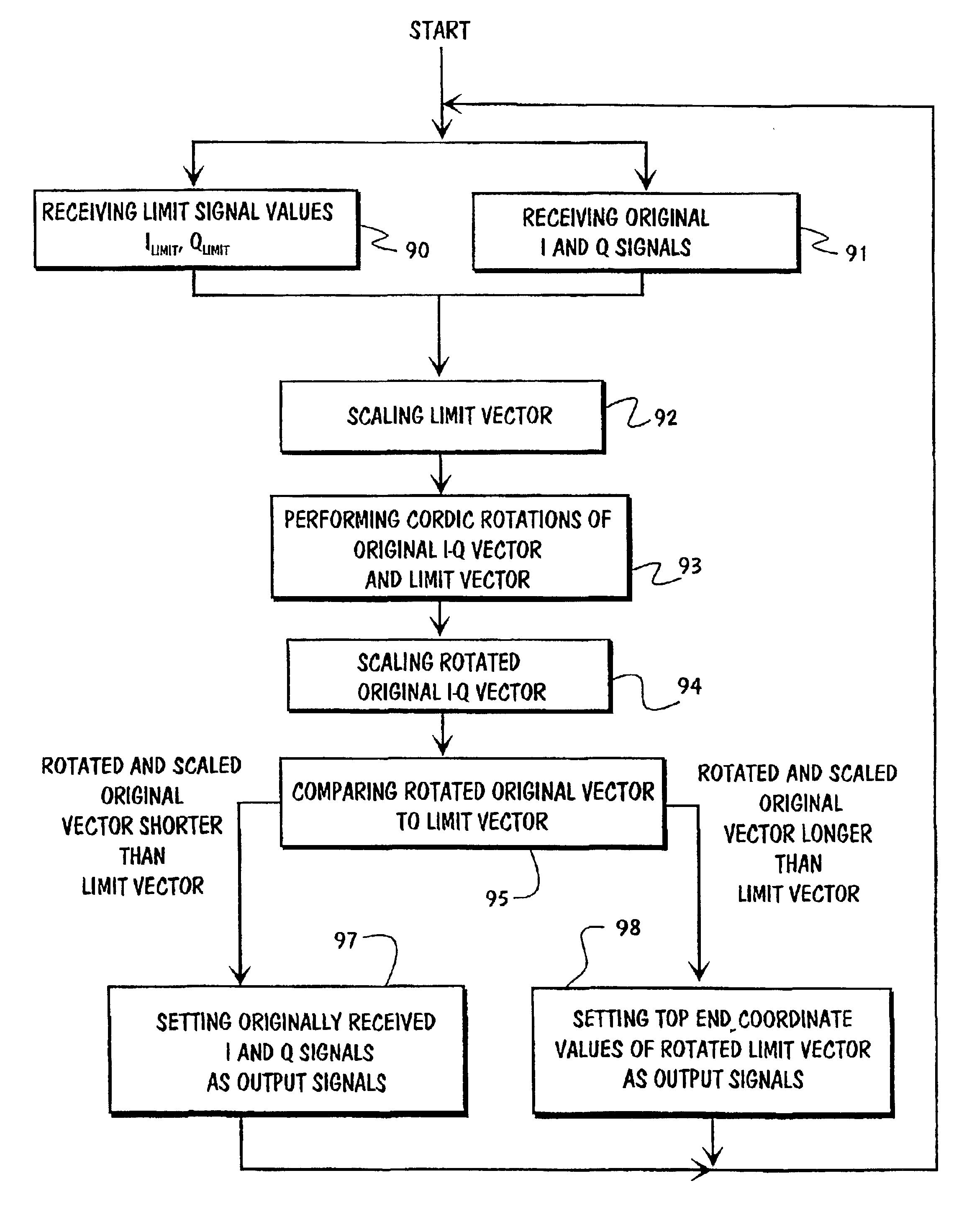
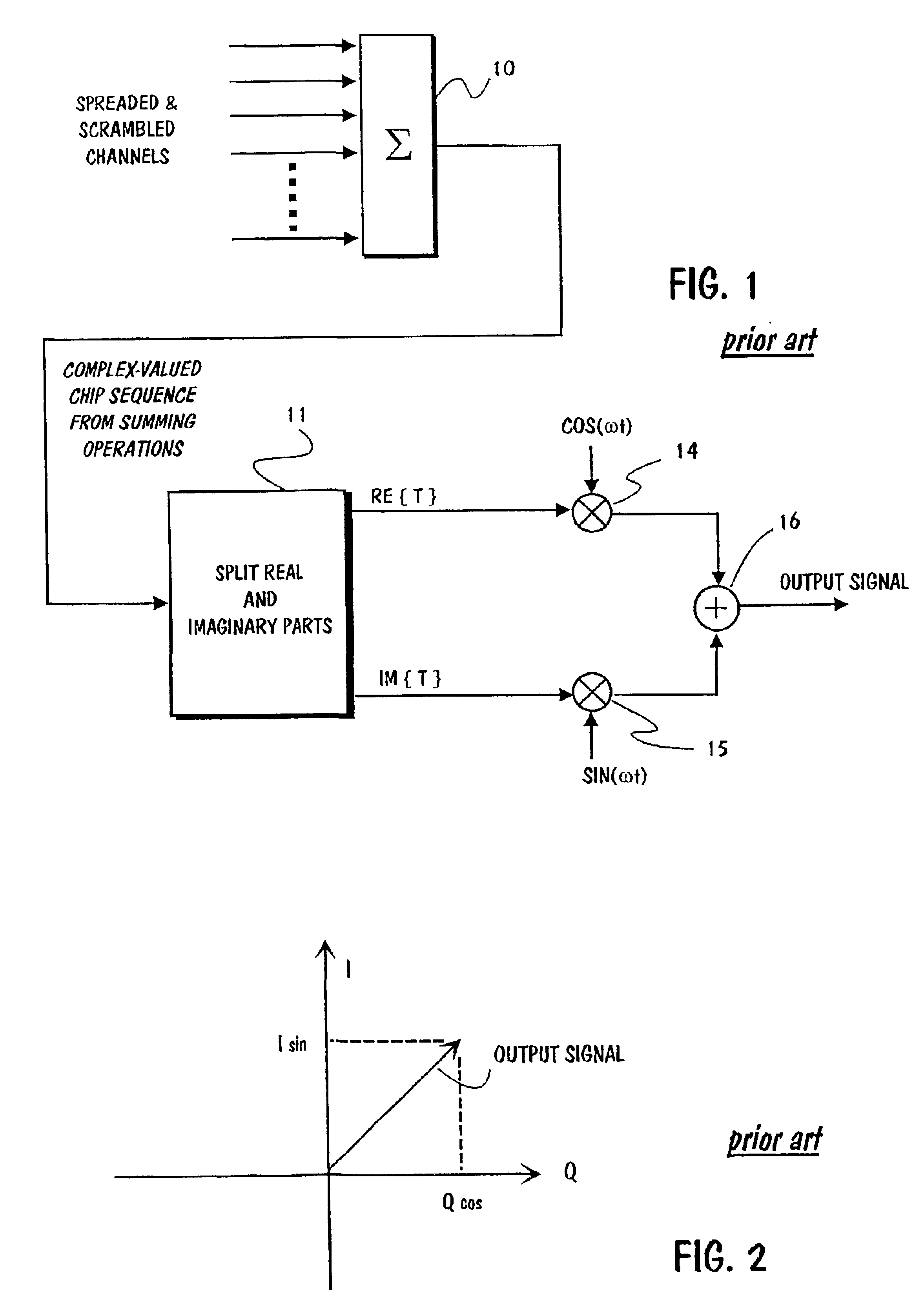
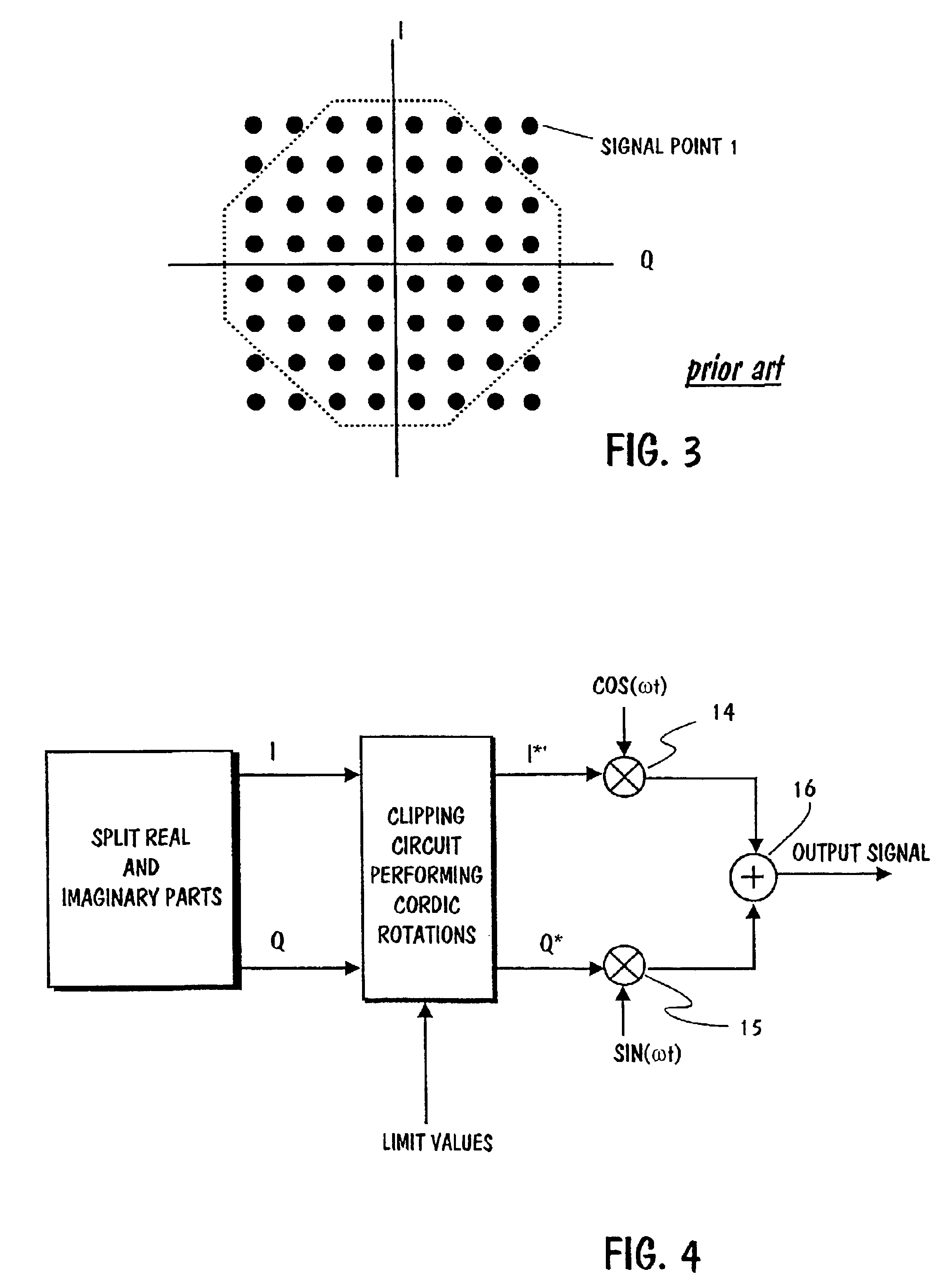
FIG. 4 illustrates the location of the clipping circuit in the modulator. As can be seen, it is located between the splitting circuit 11 and multipliers 14 and 15. Hence, I- and Q signals from the splitting circuit are input signals to the clipping circuit. Other input signals to the clipping circuit are two limit values. Output signals from clipping circuit 11 are denoted I* and Q*. Signal I* is applied to multiplier 14 and signal Q* is applied to multiplier 15.

FIG. 5 shows what the clipping circuit does to a signal point having too large amplitude. Each pair consisting of an I-signal and Q-signal forms a signal point called as a constellation point on the I-Q plane. Some signal points are denoted as black dots in the figure. Length S of the vector that starts from the origin and ends at a signal point (I,Q) is

S=√{square root over (I2+Q2)}  (4)

Hereafter such vectors are called I-Q vectors.

The previously mentioned limit values, which are also applied to inputs of the clipping circui...


PUM


Abstract

Amplitudes of signals produced by a digital modulator can be clipped so that instead of processing the output vector of the digital modulator or it's component vectors, processing is applied to the base band I and Q signals prior to modulation. The I- and Q signals are applied to an input of a clipping circuit. Predetermined limit values are also applied to another input of the clipping circuit. The clipping circuit rotates on the I-Q vector towards the limit vector. At the same time the limit vector is rotated towards the I-Q vector. Rotations are performed by using Cordic algorithm. After rotations have been completed, the rotated I-Q vector is aligned with the original limit vector, and the rotated limit is aligned with the original I-Q vector. Then the length of the rotated I-Q vector will be compared with the original limit vector. If the rotated I-Q vector is shorter than the limit vector, then the original I-Q signals are output signals from the clipping circuit. But if the rotated original I-Q vector is longer than the limit vector, then the original I-Q signals will be rejected and substituted by the coordinate values of the rotated limit vector.

Description

FIELD OF THE INVENTIONThe present invention relates generally to a method of clipping amplitudes of output signals from a digital modulator. Especially the invention relates to processing signal points arranged on a rectangular planeBACKGROUND OF THE INVENTIONOver the past several years, code-division multiple access (CDMA) systems have gained widespread interest in the mobile wireless communications field. Both a wide band code division multiple access (WCDMA) and a narrow band code division multiple access CDMA system have been presented. The WCDMA uses a wider channel compared to the narrow band system, which improves frequency diversity effects and therefore reduces fading problems.The modulation method in CDMA systems is quadrature amplitude modulation QAM. This term is used to describe the combining of two amplitude and phase modulated carriers in quadrature. Quadrature refers to a phase difference of 90 degrees between the two carriers. One of the carriers is known as the In ...

Claims


Application Information

Patent Timeline
Patent Type & Authority Patents(United States)
IPC IPC(8): H04L27/34H04L27/20H04L27/36
CPCH04L27/3411
Inventor TASKINEN, KIMMO
Owner RPX CORP
Why Eureka
Try Eureka