Turbulent flow cooling for electronic ballast

a technology of electronic ballast and cooling fluid, which is applied in the direction of discharge tube main electrodes, semiconductor devices of light sources, lighting and heating apparatus, etc., can solve problems such as turbulent ambient fluid, and achieve the effect of effectively removing hea

Active Publication Date: 2012-12-18
EXPRESS IMAGING SYST
View PDF66 Cites 110 Cited by
  • Summary
  • Abstract
  • Description
  • Claims
  • Application Information

AI Technical Summary

Problems solved by technology

The active heat transfer device causes turbulence in an ambient fluid.

Method used


Image

  • Turbulent flow cooling for electronic ballast
  • Turbulent flow cooling for electronic ballast
  • Turbulent flow cooling for electronic ballast

Examples


Embodiment Construction

[0019]In the following description, certain specific details are set forth in order to provide a thorough understanding of various disclosed embodiments. However, one skilled in the relevant art will recognize that embodiments may be practiced without one or more of these specific details, or with other methods, components, materials, etc. In other instances, well-known structures associated with lighting fixtures, power generation and / or power system for lighting have not been shown or described in detail to avoid unnecessarily obscuring descriptions of the embodiments.

[0020]Unless the context requires otherwise, throughout the specification and claims which follow, the word “comprise” and variations thereof, such as, “comprises” and “comprising” are to be construed in an open, inclusive sense that is as “including, but not limited to.”

[0021]Reference throughout this specification to “one embodiment” or “an embodiment” means that a particular feature, structure or characteristic de...


PUM


Abstract

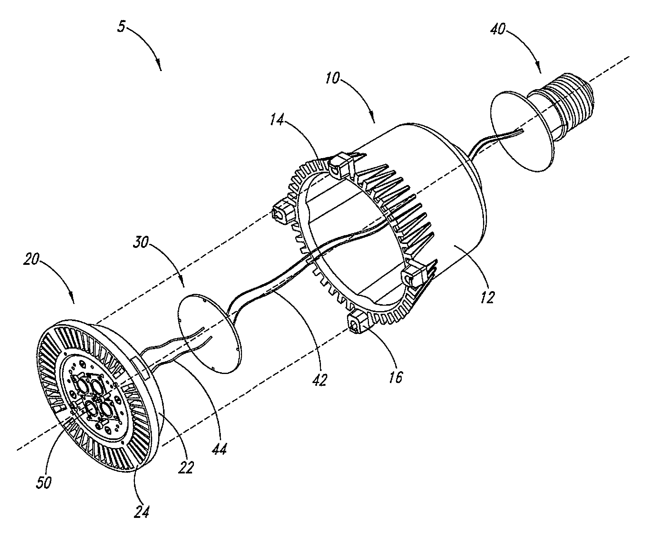
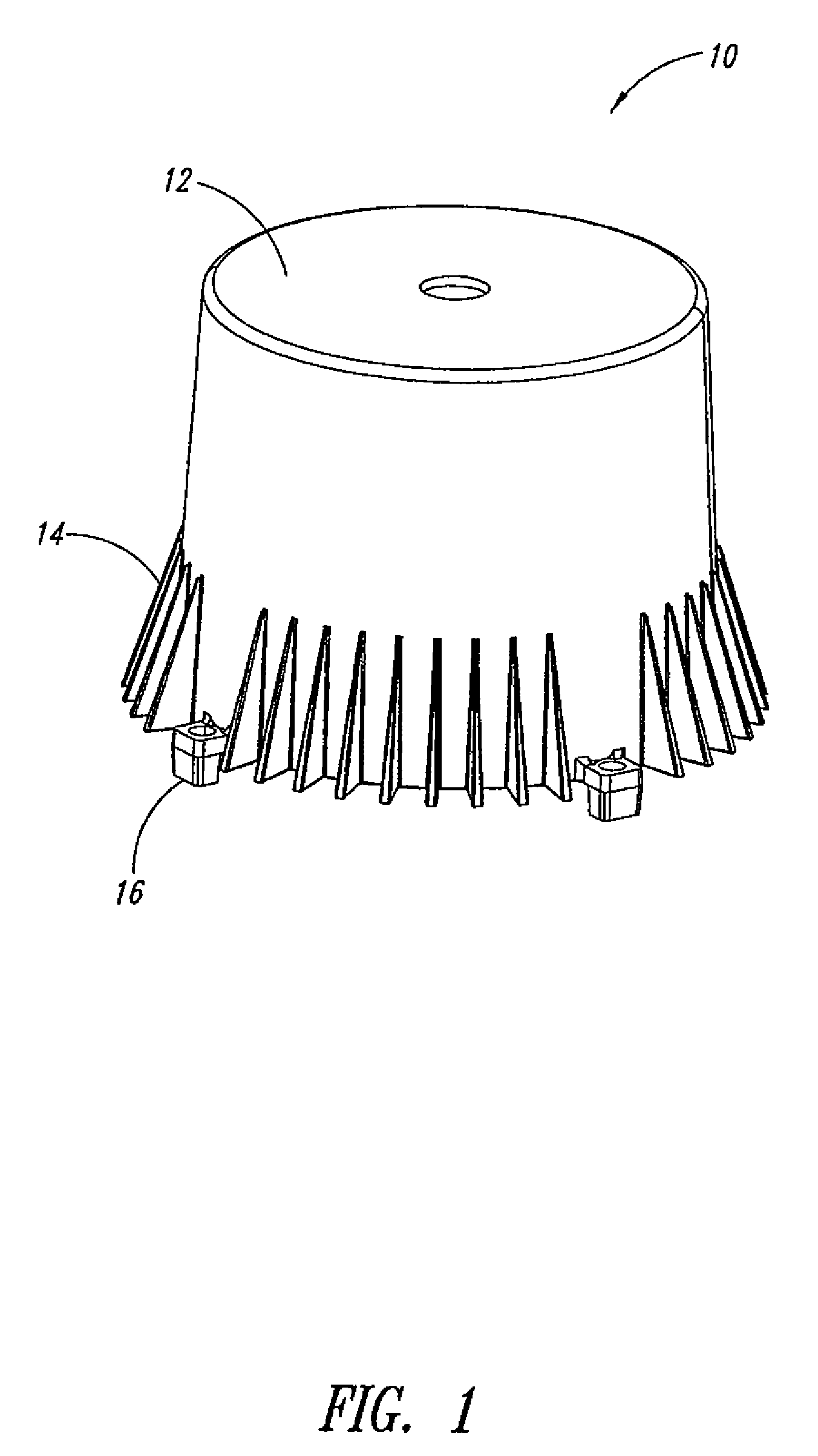
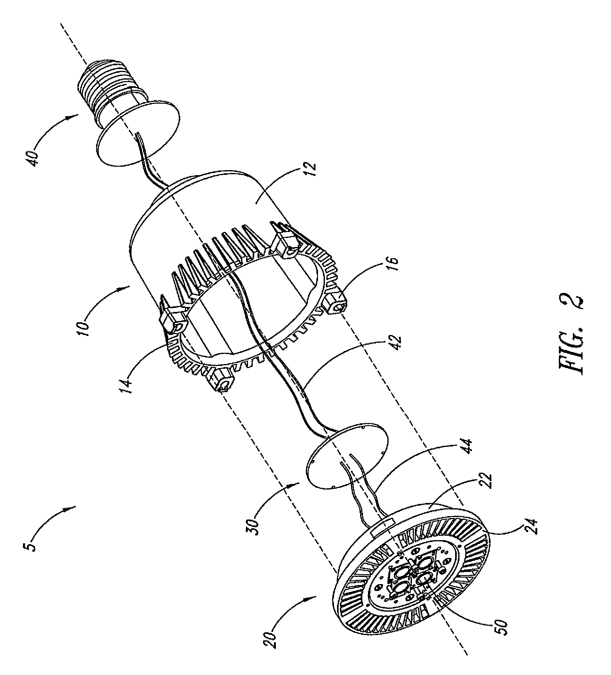
An apparatus for heat dissipation for a luminaire comprises an active heat transfer device and a thermally-conductive housing. The active heat transfer device causes turbulence in an ambient fluid. The thermally-conductive housing includes a cavity and a first end. The cavity is structured for an electronic ballast of the luminaire to be housed therein and thermally attached to an interior surface of the housing to allow the housing to absorb at least a portion of heat generated by the electronic ballast. The first end is structured for the active heat transfer device to be mountable to the first end of the housing. The housing further includes at least one thermally-conductive protrusion extending from an exterior surface of the housing and exposed to the turbulence in the ambient fluid to transfer at least a portion of the heat absorbed by the housing to the ambient fluid.

Description

CROSS REFERENCE TO RELATED APPLICATIONS[0001]This application claims benefit under 35 U.S.C. 119(e) of U.S. Provisional Patent Application Serial No. 61 / 088,651, filed Aug. 13, 2008 and entitled “Turbulent Flow Cooling for Electronic Ballast,” which is incorporated herein by reference in its entirety.BACKGROUND[0002]1. Technical Field[0003]This disclosure generally relates to the field of luminaire, and more particularly to dissipation of the heat generated by ballast electronics of a luminaire.[0004]2. Description of the Related Art[0005]With increasing trend of energy conservation and for various other reasons, including replacement of gas-vapor lamps, solid-state lighting has become more and more popular as the source of illumination in a wide range of applications. As generally known, solid-state lighting refers to a type of lighting that emits light from a solid object, such as a block of semiconductor, rather than from a vacuum or gas tube as is the case in traditional lightin...

Claims


Application Information

Patent Timeline
Patent Type & Authority Patents(United States)
IPC IPC(8): H01J7/26H01K1/58F21V29/00
CPCF21V29/004F21K9/13F21V29/40F21V29/83F21V29/507F21V29/773F21V23/026F21Y2101/02F21V29/677F21V29/60F21V29/67F21K9/23F21Y2115/10
Inventor REED, WILLIAM G.RENN, JOHN O.
Owner EXPRESS IMAGING SYST
Why Eureka
Try Eureka