Monitoring using RF communication technology

a communication technology and monitoring system technology, applied in the field of monitoring systems, can solve the problems of high false alarm rate, easy detection of coverage areas, and danger to eyes

Active Publication Date: 2013-01-15
LOCKHEED MARTIN CORP
View PDF2 Cites 36 Cited by
  • Summary
  • Abstract
  • Description
  • Claims
  • Application Information

AI Technical Summary

Problems solved by technology

Disadvantages of these security systems include high false alarm rates, danger to the eyes due to the laser light, and easily detectible coverage areas.
In addition, these system can be easily defeated, for example, when the intruder moves around the laser light.
In addition, these systems cannot detect when objects that do not emit detectable heat are removed or added to the environment.

Method used


Image

  • Monitoring using RF communication technology
  • Monitoring using RF communication technology
  • Monitoring using RF communication technology

Examples


Embodiment Construction

[0017]In the following detailed description, numerous specific details are set forth to provide a full understanding of the subject technology. It will be obvious, however, to one ordinarily skilled in the art that the subject technology may be practiced without some of these specific details. In other instances, well-known structures and techniques have not been shown in detail to avoid obscuring concepts of the subject technology.

[0018]Reference will now be made in detail to aspects of the subject technology, examples of which are illustrated in the accompanying drawings, wherein like reference numerals refer to like elements throughout.

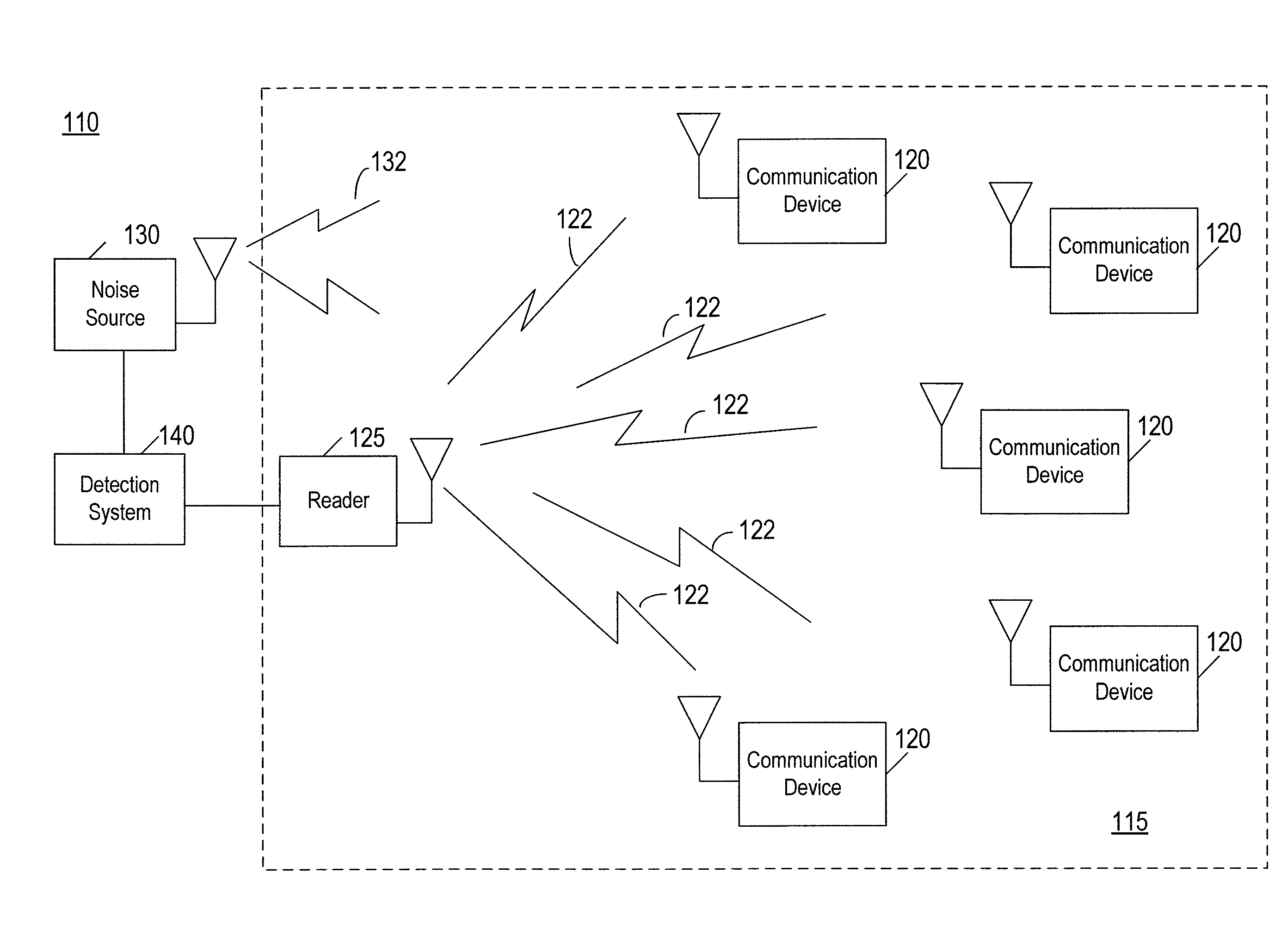
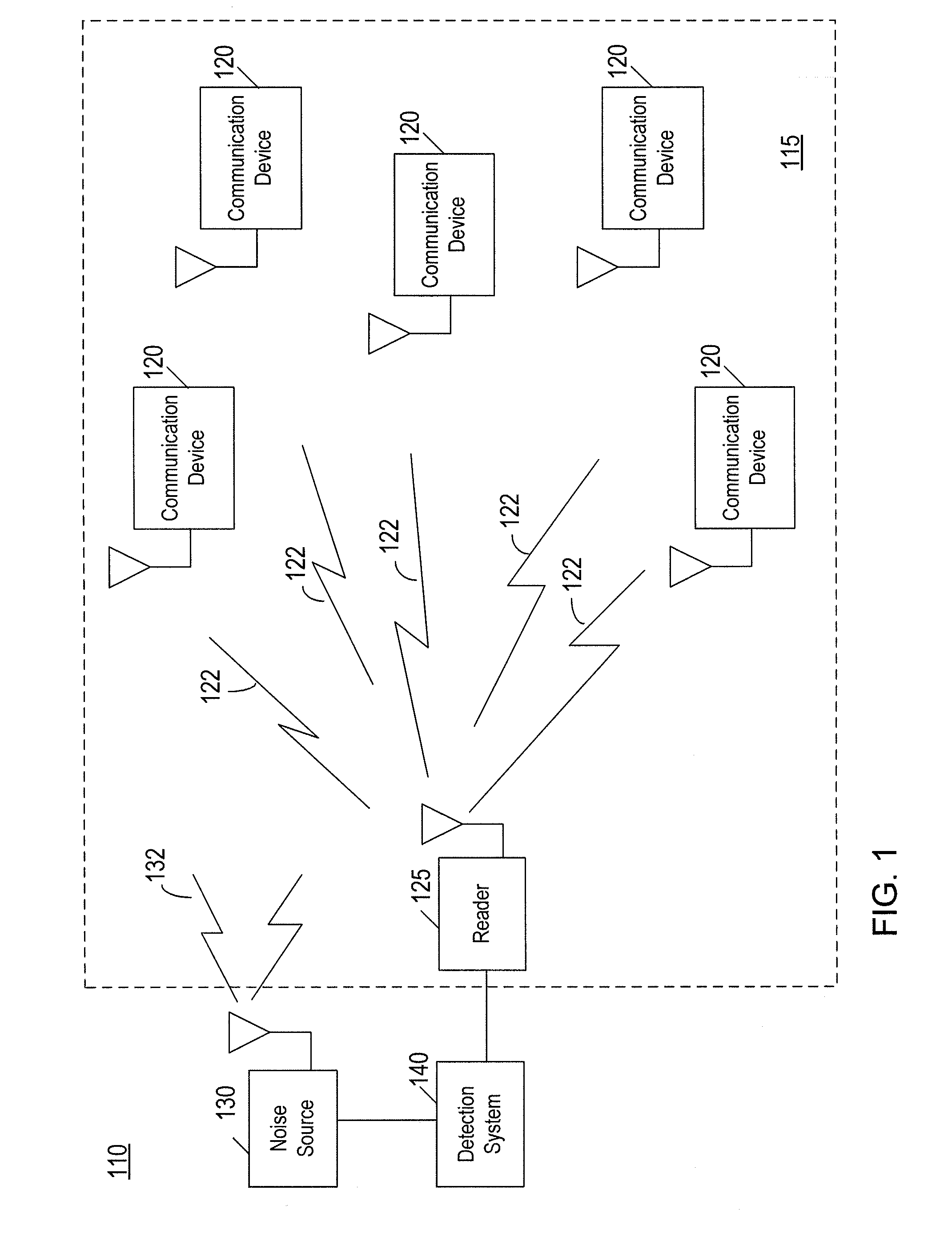
[0019]FIG. 1 is a conceptual block diagram of a monitoring system 110 according to an aspect of the present disclosure. The monitoring system 110 comprises a communication system 115. The communication system 115 comprises one or more communication devices 120 distributed in an environment being monitored and an interrogator 125 in communication wi...


PUM


Abstract

Systems and methods for detecting change in an environment are provided. In one aspect, a system for detecting change in an environment includes an RF noise source configured to transmit an RF noise signal into the environment and to vary a parameter of the RF noise signal, and an interrogator configured to communicate with a plurality of communication devices distributed in the environment over a plurality of communication channels. The system also includes a detection system configured to receive information related to performances of the plurality of communication channels from the interrogator, to generate a fingerprint of the environment for each of the plurality of communication channels based on the performance of the communication channel at different values of the parameter of the RF noise signal, and to detect a change in the environment when one or more of the fingerprints deviates from a respective baseline fingerprint by a certain amount.

Description

RELATED APPLICATION[0001]The present application claims the benefit of priority under 35 U.S.C. §119 from U.S. Provisional Patent Application Ser. No. 61 / 080,637, entitled “MONITORING USING RF COMMUNICATION TECHNOLOGY,” filed on Jul. 14, 2008, which is hereby incorporated by reference in its entirety for all purposes.STATEMENT REGARDING FEDERALLY SPONSORED RESEARCH OR DEVELOPMENT[0002]Not Applicable.FIELD OF THE INVENTION[0003]This disclosure relates generally to monitoring systems and, more particularly to monitoring systems using RF communication technology.BACKGROUND OF THE INVENTION[0004]Security systems may be employed to detect an intruder in an environment under surveillance. Examples of security systems include systems using laser light, in which an intruder is detected by a break in a laser light caused by the intruder. Disadvantages of these security systems include high false alarm rates, danger to the eyes due to the laser light, and easily detectible coverage areas. In ...

Claims


Application Information

Patent Timeline
Patent Type & Authority Patents(United States)
IPC IPC(8): G08B1/08
CPCG08B13/187
Inventor LIBBY, VIBEKECAMP, JOHN S.
Owner LOCKHEED MARTIN CORP
Why Eureka
Try Eureka