Ambidextrous rifle bolt stop release

a technology of bolt stop release and rifle, which is applied in the direction of breech mechanism, weapon components, weapon components, etc., can solve the problems of difficult single-hand use, limited configuration, and problematic left-hand use of the firearm

Active Publication Date: 2013-01-29
TEAL BLUE BRAVO
View PDF9 Cites 71 Cited by
  • Summary
  • Abstract
  • Description
  • Claims
  • Application Information

AI Technical Summary

Benefits of technology

[0004]The invention includes a method of modifying a M16 / M4 rifle to provide a second bolt stop release operable from the right side of the rifle. The second bolt stop release is a rigid extension of the bolt stop that passes through the right-side receiver wall to a position accessible to a user gripping the rifle with the user's right hand in conventional firing position. The inventive method includes modification of existing rifle bolt stop, and also replacement with a bolt stop with the inventive configuration.

Problems solved by technology

This configuration is limiting and is often difficult to use with a single hand while aiming the firearm.
As well, this configuration is problematic for left-hand use of the firearm.

Method used


Image

  • Ambidextrous rifle bolt stop release
  • Ambidextrous rifle bolt stop release
  • Ambidextrous rifle bolt stop release

Examples


Embodiment Construction

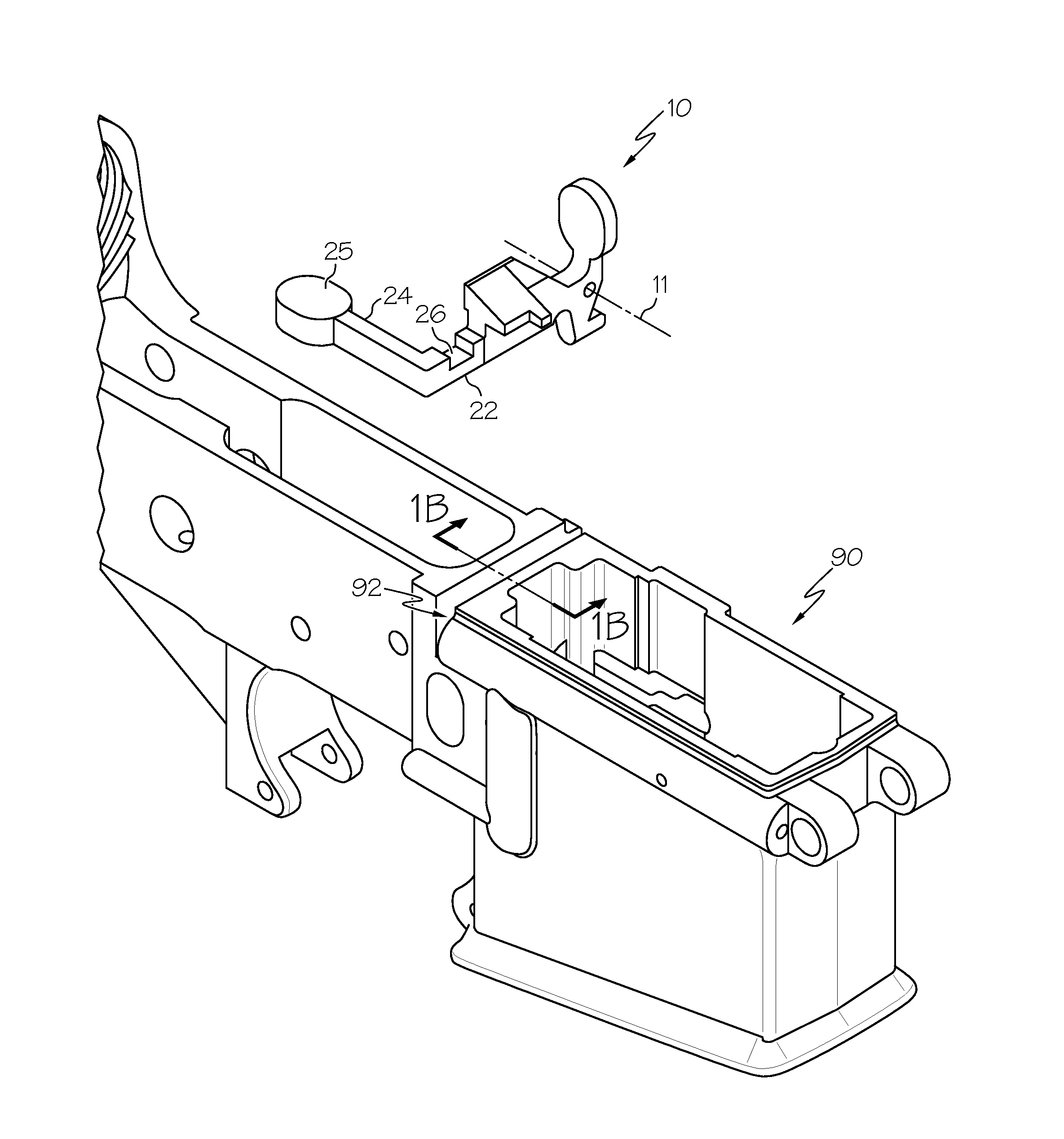
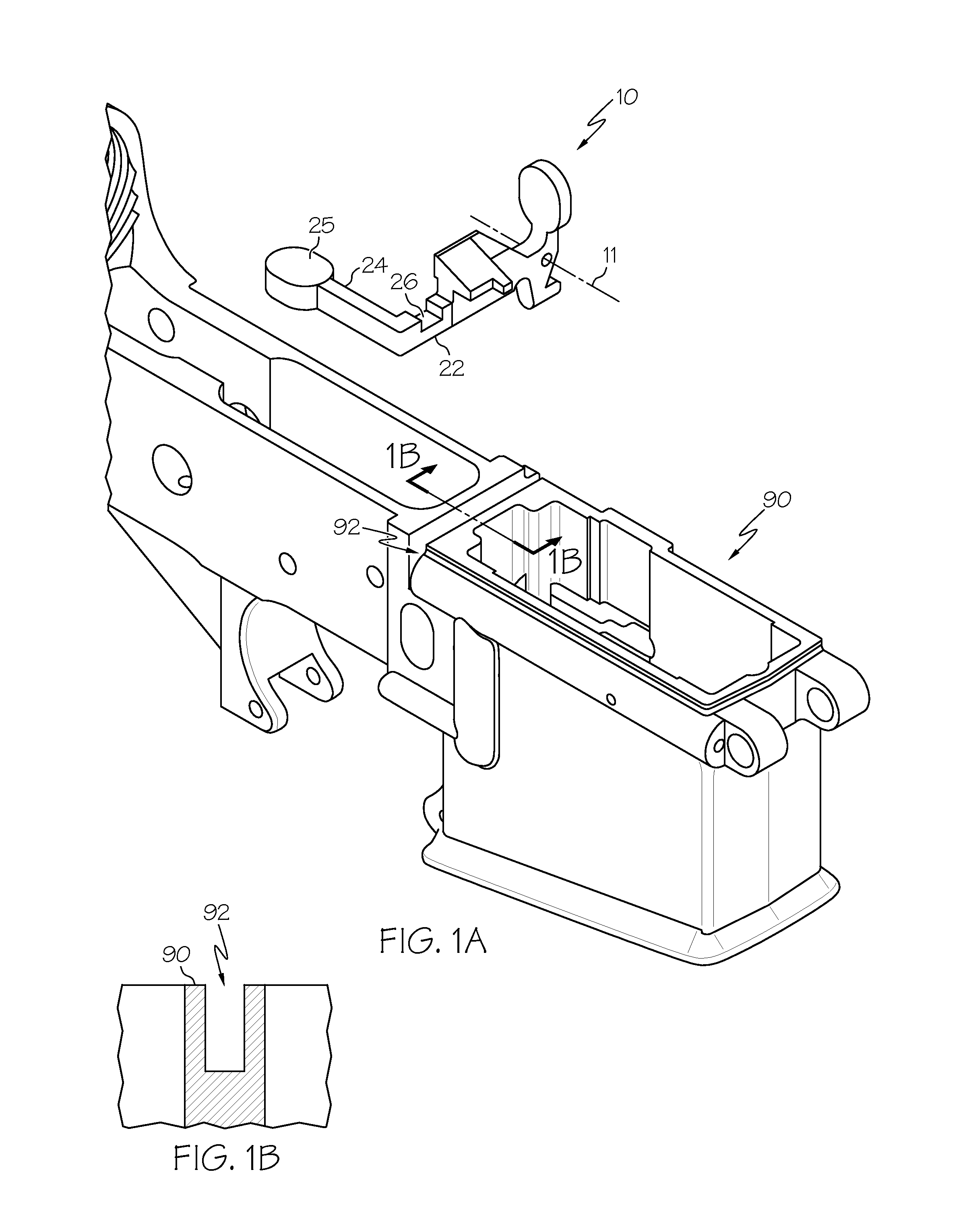
[0009]The operation of the conventional bolt stop and its release function in the M16 / M4 rifle is well known and understood. While the rifle bolt is held back by a bolt stop, to allow the bolt to move forward the bolt stop must be rotated downward about a pivot pin and against the bias of a spring.

[0010]In the present invention, the bolt stop is modified to enable the present invention, or an inventive replacement bolt stop is provided and assembled with the rifle in place of the original bolt stop. Either method will provide the same result and enable the inventive objectives and functions.

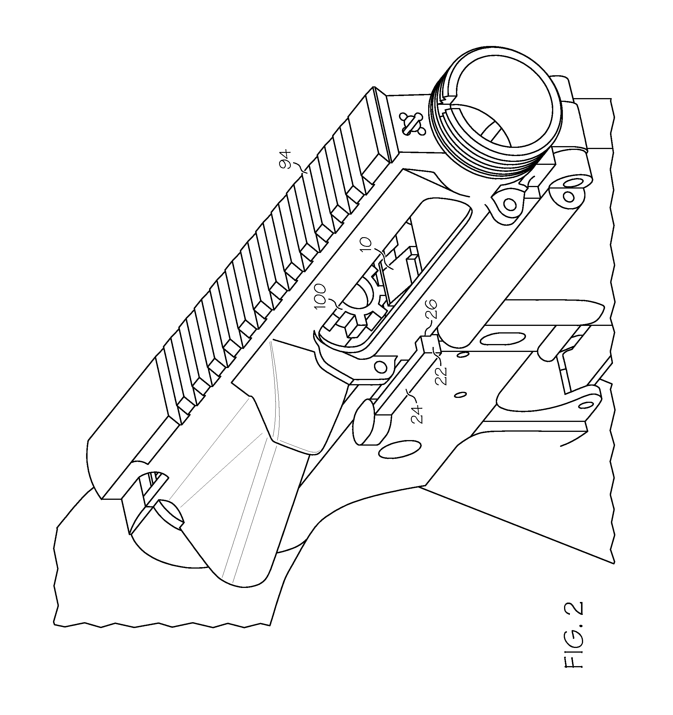
[0011]FIGS. 1A, 1B, 2 and 3 illustrate a rifle receiver and bolt according to the invention. The rifle barrel and various other conventional components have been removed for clarity and simplicity. The elements and configurations shown will be familiar to those skilled in the art with experience with the M16 / M4 rifles. FIG. 1A illustrates the inventive bolt stop 10 shown separated from and above ...


PUM


Abstract

A method of modifying a rifles of the M16, M4, AR15 platform provides a second bolt stop release operable from the right side of the rifle. The second bolt stop release is a rigid extension of the bolt stop that passes through the right receiver wall to a position accessible to a user gripping the rifle with the user's right hand in conventional firing position. The two bolt stop releases provide the inventive rifle ambidextrous bolt release operation.

Description

BACKGROUND OF THE INVENTION[0001]The present invention pertains to mechanisms in firearms that control or limit the movement of the firearm “bolt” element. In many typical firearm designs, a magazine is used to store and feed ammunition into a firing chamber. In many manual as well as semi and fully automatic firearms, a bolt moves backward and forward between each shot, propelled by recoil or expanding gas or a recoil spring. When the bolt moves forward, it moves a cartridge from the magazine and pushes it into the chamber. During firing, the bolt blocks and seals the chamber. When the bolt moves back, the spent ammunition casing is removed from the chamber and ejected from the firearm. Typically, after the last round in the magazine is fired, a floor plate of the magazine is pushed upward by spring action to contact and lift a bolt “stop” or “catch” that is mounted within the firearm receiver. In this lifted position, the bolt stop holds the bolt rearward of the magazine to allow ...

Claims


Application Information

Patent Timeline
Patent Type & Authority Patents(United States)
IPC IPC(8): F41A3/42
CPCF41A3/68F41A17/36
Inventor BROTHERTON, WILLIAM A.
Owner TEAL BLUE BRAVO
Why Eureka
Try Eureka