Spinning reel for fishing

a spinning reel and reel body technology, applied in fishing, reels, applications, etc., can solve the problems of rotational sensitivity or smoothness, moment of inertia, and worsen so as to improve the rotational performance of the rotor. , the effect of increasing the moment of inertia

Active Publication Date: 2013-02-26
DAIWA SEIKO CORPORATION
View PDF13 Cites 4 Cited by
  • Summary
  • Abstract
  • Description
  • Claims
  • Application Information

AI Technical Summary

Benefits of technology

[0006]Further more, the rotor of a spinning reel for fishing includes several devices or components mounted such as a fishing line guide part for guiding a fishing line into a spool, a press retaining device for shifting, and then retaining, the fishing line guide part between a fishing line winding state and a fishing line releasing state, a reverse device for retrieving from the fishing line releasing state to the fishing line winding state, and a bail for conveying the fishing line to the fishing line guide part, being accompanied by the reverse retrieving from the fishing line releasing state to the fishing line winding state. Accordingly, the weight of the rotor itself increases, and, thus, the moment of inertia also becomes higher. In addition to the seal resistance, the increased moment of inertia due to the increased weight is considered as a factor deteriorating the rotational sensitivity of the rotor.
[0007]One aspect of the exemplary embodiment is encouraged in consideration of these problems, and is to provide a spinning reel for fishing for improving the rotational performance of a rotor by reducing the moment of inertia of the rotor.

Problems solved by technology

Thus, there is a problem of worsening the rotational performance of the rotor, such as the rotational sensitivity or the smoothness.
In addition to the seal resistance, the increased moment of inertia due to the increased weight is considered as a factor deteriorating the rotational sensitivity of the rotor.

Method used


Image

  • Spinning reel for fishing
  • Spinning reel for fishing
  • Spinning reel for fishing

Examples


Embodiment Construction

[0049]Hereinafter, a fishing reel according to an exemplary embodiment is described in detail with reference to the accompanying drawings.

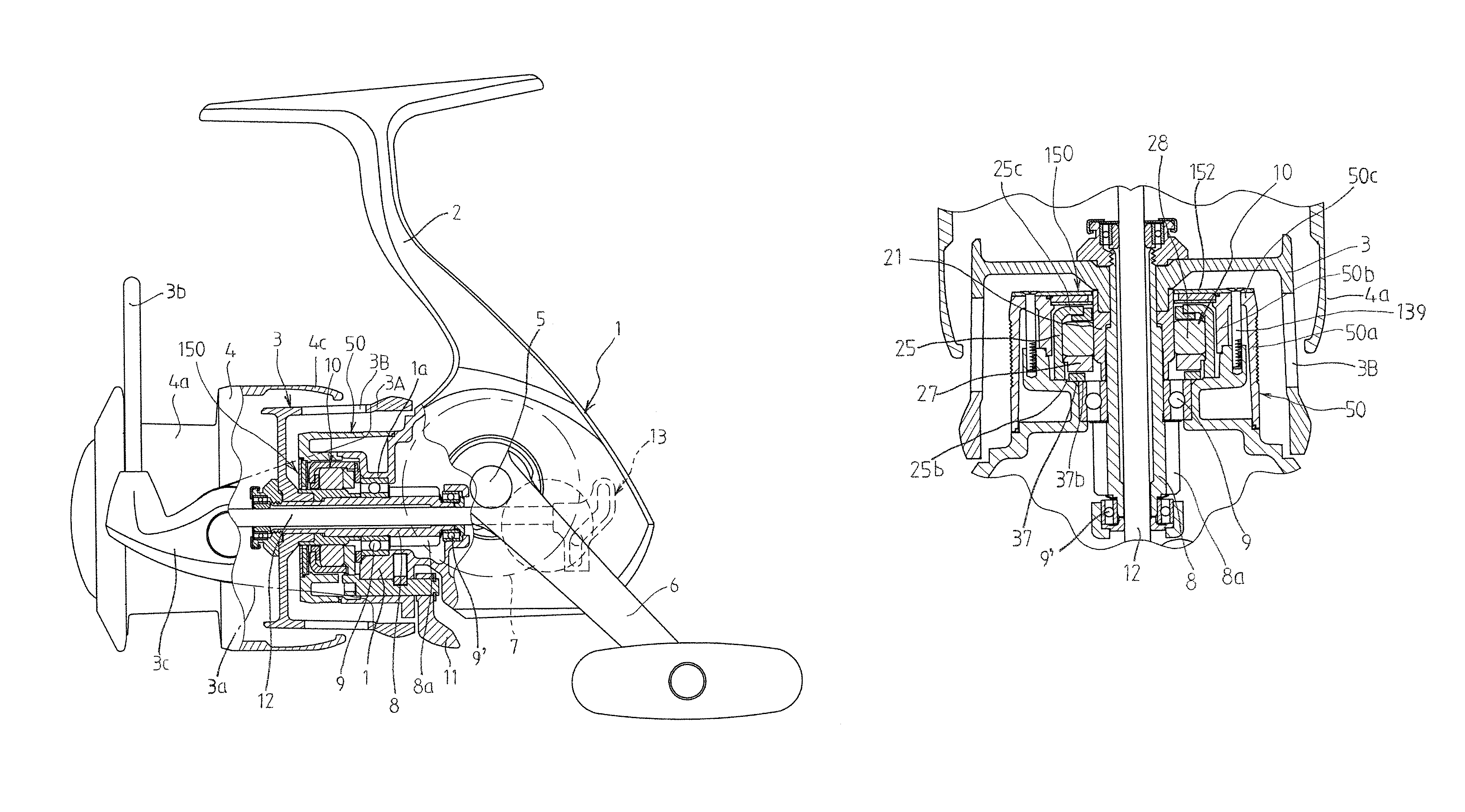
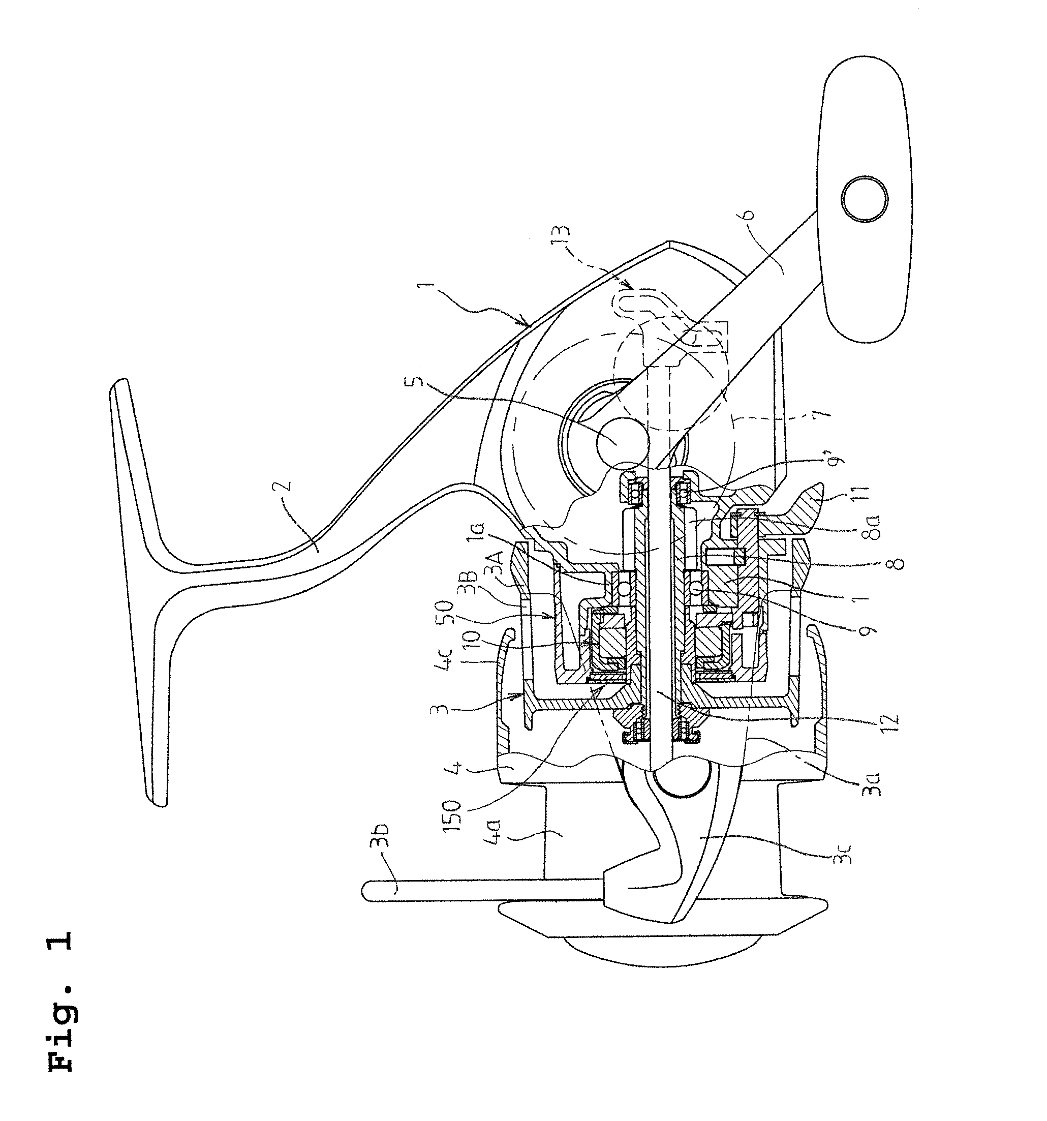
[0050]FIGS. 1 to 9 illustrate the spinning reel for fishing according to a first embodiment. A reel body 1 (made of, for example, metal) includes a reel foot 2 integrally formed with the reel body 1, a rotor 3 rotatably supported in the front of the reel body 1, and a spool 4 supported moveably back and forth in association with the rotation of the rotor 3.

[0051]The rotor 3 includes a pair of arms 3a (only one is shown in FIG. 1) rotatable around the spool 4. Each arm 3a includes a bail support member 3c in the front end of the arm 3a in such a way that the bail support member 3c can freely rotate between a fishing line winding position and a fishing line releasing position. The bail support members 3c attaches the base ends of the bail 3b therewith. One base end of the bail 3b is attached to a fishing line guide part 3d (See FIG. 6) integrally pr...


PUM


Abstract

A spinning reel for fishing includes: a reel body including a front portion; a handle provided in the reel body; a cap-shaped cover body including a surrounding wall mounted in the front portion of the reel body; a spool on which a fishing line is to be wound; a rotor including a fishing line guide part, the rotor being rotated by the rotational manipulation of the handle to wind the fishing line on the spool; a driving part passing through the cover body and transmitting the rotation of the handle to the rotor; a support part provided in the front portion of the reel body and supporting the driving part; and a magnetic seal device mounted in the cover body and including a magnet, a cylindrical magnetic body forming a magnetic circuit between the magnetic body and the magnet and magnetic fluid maintained between the magnet and the magnetic ring.

Description

BACKGROUND ART[0001]The disclosure relates to a spinning reel for fishing for reeling a fishing line in a spool by the rotational operation of a rotor having a fishing line guide part, which is cause by the rotational manipulation of a handle provided in a reel body.[0002]A spinning reel for fishing reels a fishing line in a spool via a fishing line guide part of a rotor, which is associated with, and rotated by, the rotational manipulation of a handle.[0003]A fishing spinning reel is used outdoors, the severe environment where sea water or fresh water may easily wet, or permeate, the reel. Thus, the corrosion of a support portion of an operation member, which deteriorates the rotational performance of the reel, should be prevented.[0004]Japanese Patent No. 4057254 discloses the structure for achieving the waterproof of a bearing part of an operation member by providing a retaining member with a seal member. The retaining member retains the bearing part of the operation member in th...

Claims


Application Information

Patent Timeline
Patent Type & Authority Patents(United States)
IPC IPC(8): A01K89/01
CPCA01K89/01A01K89/0117A01K89/011221
Inventor SHIBATA, TAKASHIFUJIOKA, MASASHI
Owner DAIWA SEIKO CORPORATION
Why Eureka
Try Eureka