
Packing insert for disc-shaped objects

a technology for inserts and discs, applied in the field of inserts for discs, can solve the problems of thinning the wafer further affecting the quality of the disc, and the difficulty of storing the disc,

Active Publication Date: 2013-03-12
TEXAS INSTR INC
View PDF13 Cites 9 Cited by
  • Summary
  • Abstract
  • Description
  • Claims
  • Application Information

AI Technical Summary

Problems solved by technology

Additionally, wafers may be lapped, resulting in further thinning of the wafers.
The trend towards larger, more dense and thinner wafers, has resulted in the wafers becoming more valuable, more brittle, more easily damaged during shipment.
Although it is possible to ship thicker wafers in enclosed containers that would support the wafers exclusively by their edges, using such devices to ship these thinner wafers has proven problematic due to breakage and damage of the wafers.
However, this type of packing methodology can increase the usage rate of packing materials and thus the costs for packing the wafers.
Furthermore, the resulting packing procedure is typically inefficient as a longer amount of time is necessary to determine and stack the needed number of inserts into the container.
In addition, such inserts may move during shipping and cause wafer damage.
As previously described, one of the main inefficiencies in the packing of disc-shaped objects is the need to provide additional insert materials when packing a container for disc-shaped objects with less objects than the container was designed for.
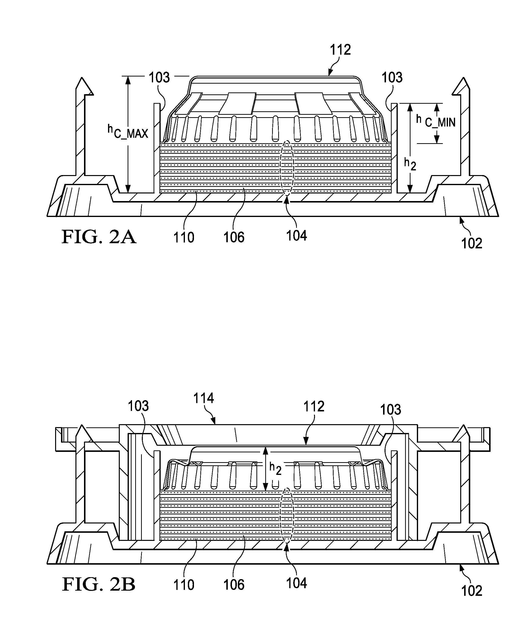
However, in such embodiments, the number of disc-shaped object that can be stored in a container is limited as the compressed height of the packing insert is increased.
In addition to stabilizing the disc-shaped objects within the container, potential damage from the packing insert can also be limited.
That is, in the case of disc-shaped objects that can be easily damaged, the amount of contact between the packing insert and the disc-shaped objects can be limited.
For example, in the case of semiconductor wafers, the stiffness can be limited to prevent the packing insert from placing too much force on the wafers and resulting in breakage.
In the case of more fragile disc-shaped objects, this can result in breakage during shipments.
As previously described, the amount of contact between a packing insert and the disc-shaped objects can be limited.

Method used


Image

  • Packing insert for disc-shaped objects
  • Packing insert for disc-shaped objects
  • Packing insert for disc-shaped objects

Examples


Embodiment Construction

[0014]The present invention is described with reference to the attached figures, wherein like reference numerals are used throughout the figures to designate similar or equivalent elements. The figures are not drawn to scale and they are provided merely to illustrate the instant invention. Several aspects of the invention are described below with reference to example applications for illustration. It should be understood that numerous specific details, relationships, and methods are set forth to provide a full understanding of the invention. One having ordinary skill in the relevant art, however, will readily recognize that the invention can be practiced without one or more of the specific details or with other methods. In other instances, well-known structures or operations are not shown in detail to avoid obscuring the invention. The present invention is not limited by the illustrated ordering of acts or events, as some acts may occur in different orders and / or concurrently with o...


PUM

PropertyMeasurementUnit
lengthaaaaaaaaaa
lengthaaaaaaaaaa
outer diameteraaaaaaaaaa

Abstract

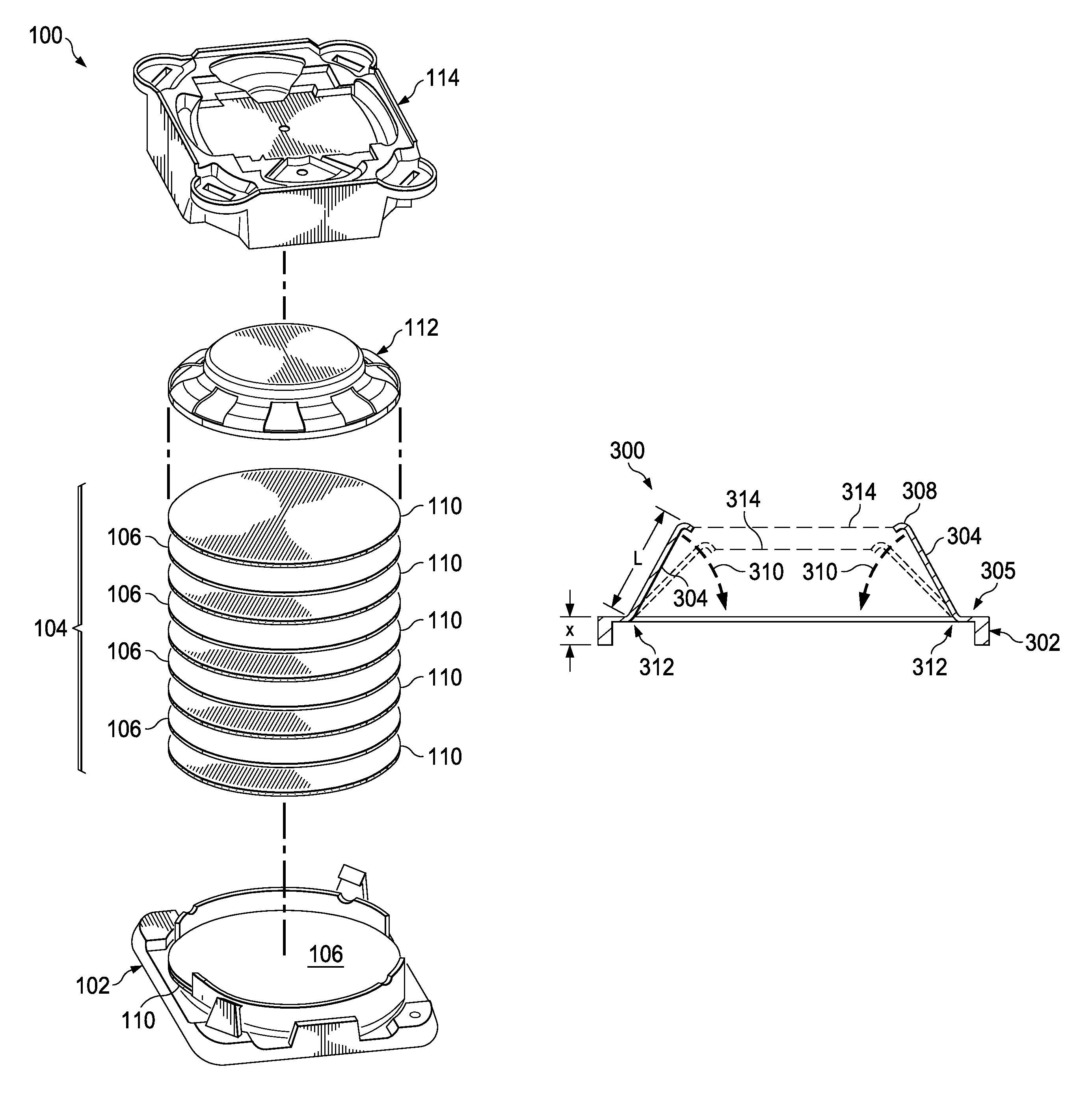
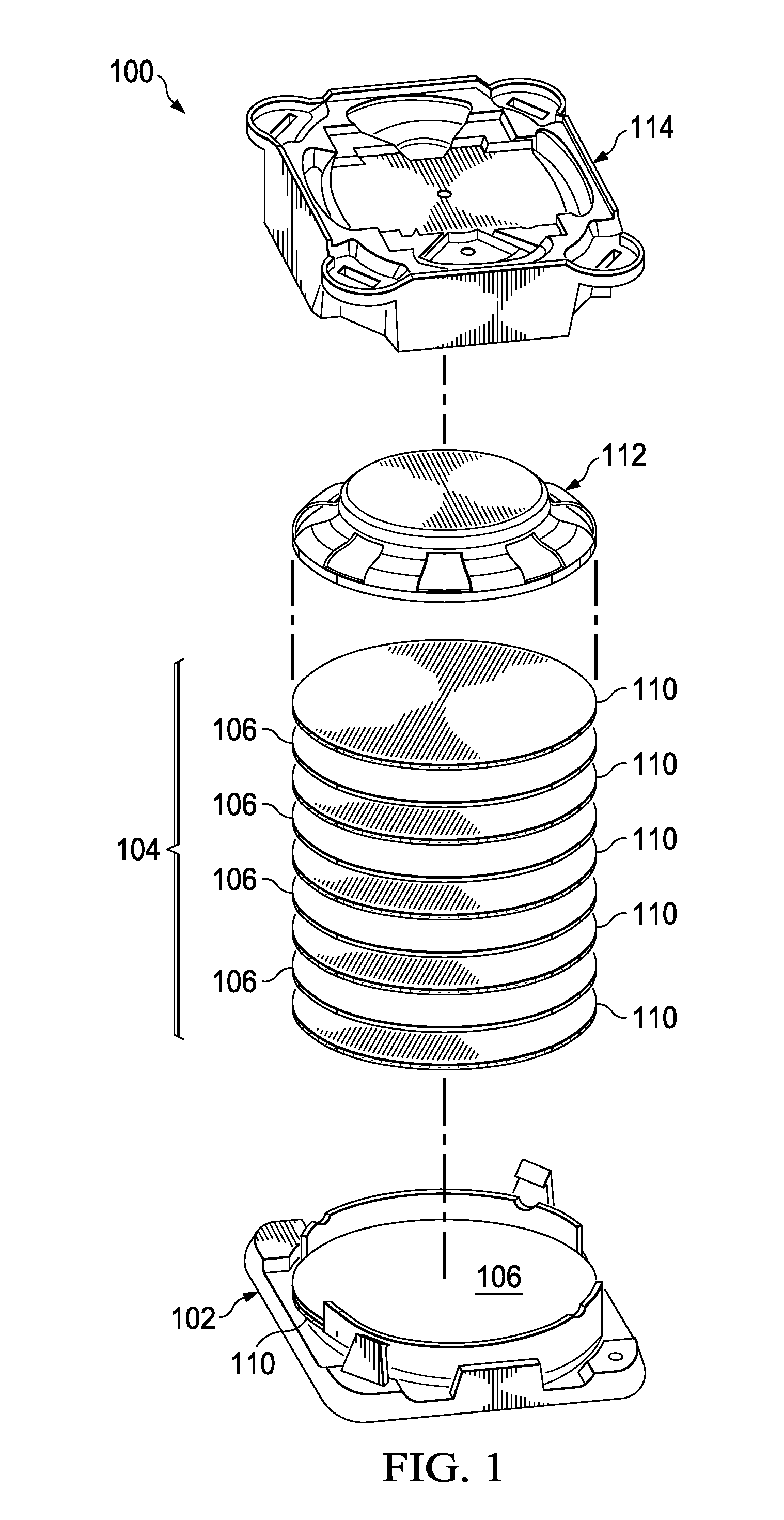
A described packing insert for disc-shaped objects has a ring and a deformable contacting portion supported by the ring and extending from a circumference of the ring. The contacting portion has one or more solid portions extending from the circumference. The solid portions define a plurality of radially arranged members separated by a plurality of void regions, where the solid portions extend radially from a circumference of the ring.

Description

FIELD OF THE INVENTION[0001]The present invention is related to the field of packing disc-shaped objects and more particularly, to inserts for packing disc-shaped objects.BACKGROUND[0002]Typically, integrated circuits are manufactured from semiconductor wafers that are conventionally round in shape and made of thin, brittle substrates. Additionally, wafers may be lapped, resulting in further thinning of the wafers. Traditionally, during the processing, storage, and shipping of semiconductor wafers the wafers are supported and constrained at their edges to prevent any contact and possible damage and contamination to the faces of the wafers having the circuits thereon. The trend towards larger, more dense and thinner wafers, has resulted in the wafers becoming more valuable, more brittle, more easily damaged during shipment. Although it is possible to ship thicker wafers in enclosed containers that would support the wafers exclusively by their edges, using such devices to ship these t...

Claims


Application Information

Patent Timeline
Patent Type & Authority Patents(United States)
IPC IPC(8): B65D85/30
CPCH01L21/67369H01L21/67386B65B5/08
Inventor OCHOA, ROLANDOTAMEZ, ISMAELESCUSA, ALBERT WINSTON D.
Owner TEXAS INSTR INC
Learn More