Medical instrument with multi-joint arm

a multi-joint arm and medical instrument technology, applied in the field of medical instruments, can solve the problems of limited pivoting ability of the end-piece and problem of force transmission from the handle to the movable instrument part on the pivotable end piece, and achieve the effect of efficient force transmission

Inactive Publication Date: 2013-03-19
RICHARD WOLF GMBH
View PDF14 Cites 662 Cited by
  • Summary
  • Abstract
  • Description
  • Claims
  • Application Information

AI Technical Summary

Benefits of technology

[0008]Due to the forced guiding, the pivoting of the individual arm parts of the multi-joint arm is defined when pivoting the pivotable instrument section, and in cooperation with the selection of a suitable number of arm parts and suitable arm part dimensions, may advantageously be selected such that the multi-joint arm, at least for the most part, is arranged within the inner cross section of the hollow shank and pivotable instrument section, during the pivoting and after the pivoting, and a particularly efficient force transmission is made possible from the actuator guided in the hollow shank to the instrument part which is movably mounted in the pivotable instrument section. Advantageously, the multi-joint arm may transmit compression forces and tensile forces from the actuator onto the instrument part movably mounted in the pivotable instrument section, to the same extent even in the bent condition.

Problems solved by technology

However, with these instruments, and with a pivoted (angled) end piece, the force transmission from the handle to the movable instrument part on the pivotable end piece has been found to be problematic, since only relatively small forces may be transmitted by an actuation element in the hollow shank to the movable instrument part.
The pivoting ability of the end-piece is limited, however, due to the fact that the control wires, which bend transversely to their longitudinal axis with the pivoting of the end-piece, may not be bent up to a kinking limit, since the end-piece may no longer be pivoted back if the control wire is kinked.

Method used


Image

  • Medical instrument with multi-joint arm
  • Medical instrument with multi-joint arm
  • Medical instrument with multi-joint arm

Examples


Embodiment Construction

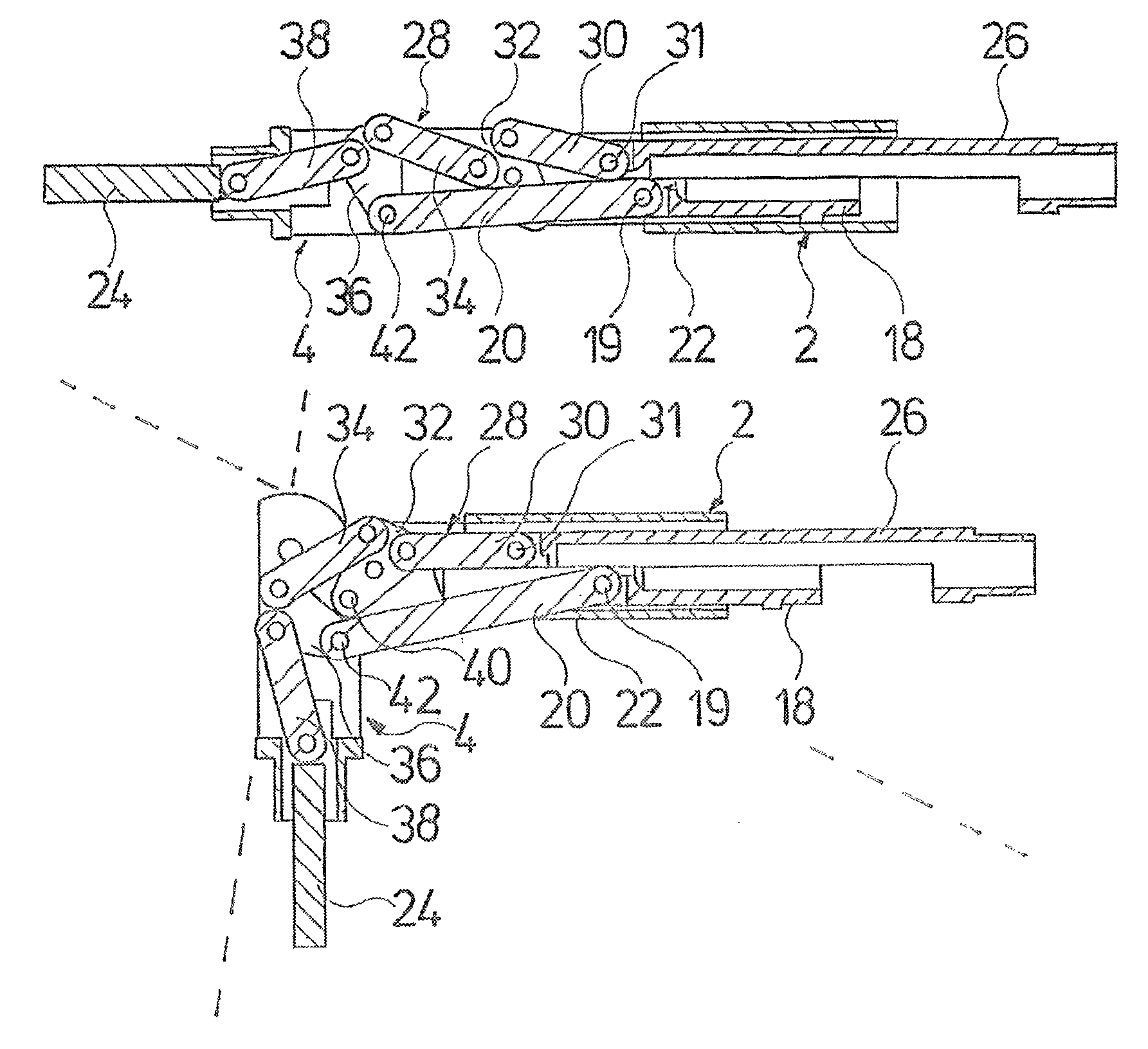
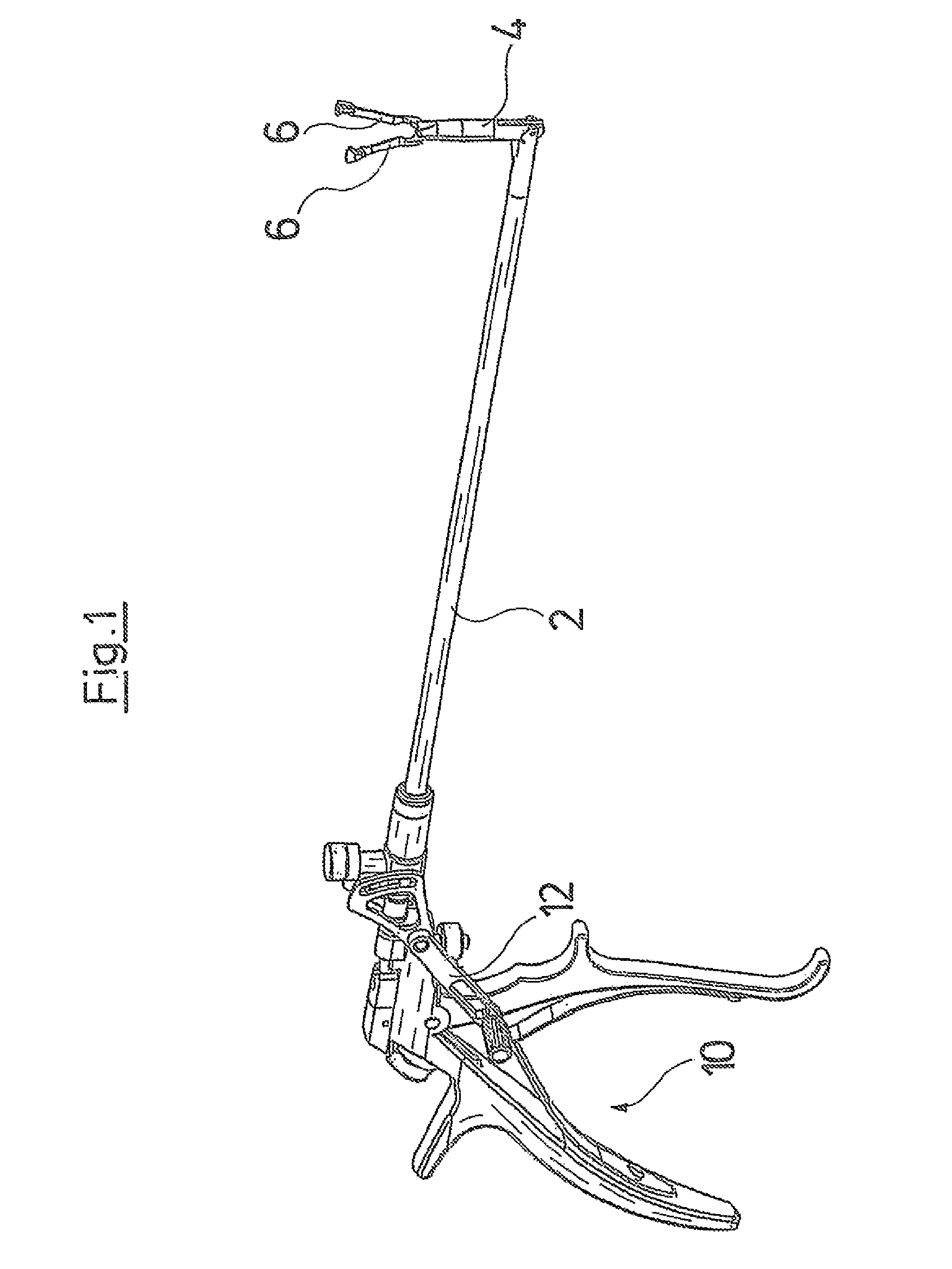
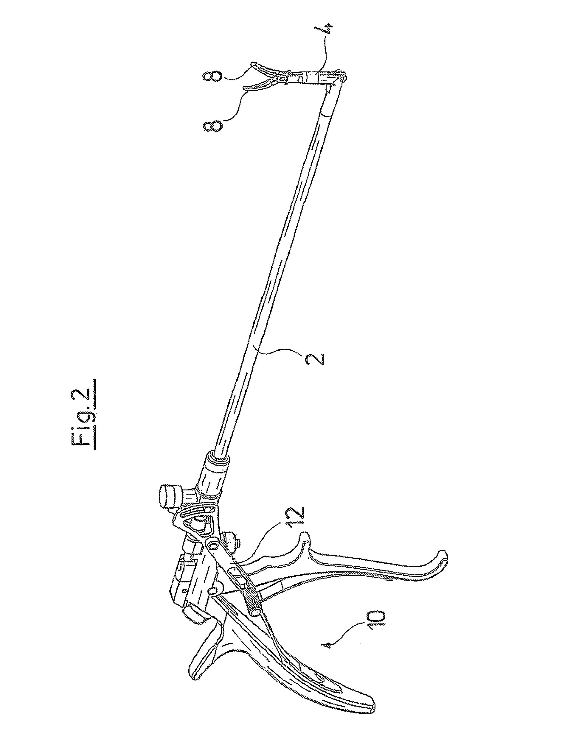
[0033]The medical gripper forceps represented in FIG. 1 and the medical scissors represented in FIG. 2 respectively comprise a hollow shank 2, which is formed of a rigid, straight tube. In the vicinity of the distal end of the hollow shank 2, a respective instrument section 4 is articulated on this hollow shank in a pivotable manner over an angular range of essentially up to 90° transversely to a longitudinal axis of the hollow shank 4. In the region of the distal end of the instrument section 4, branches 6 of the gripper forceps represented in FIG. 1 and blades 8 of the scissors represented in FIG. 2 are mounted in a pivotably movable manner. The branches 6 or the blades 8 are coupled in movement to a handle 10, which is arranged on the proximal end of the hollow shank 2, by an actuator arranged in the instrument section 4 and the hollow shank 2, and this actuator will be discussed in more detail hereinafter. Moreover, a further actuator is arranged on the instrument section 4 and ...


PUM


Abstract

A medical instrument includes a hollow shank and an instrument section arranged pivotable to the hollow shank proximate the distal end of this hollow shank. An instrument part is mounted in an axially movable manner in the pivotable instrument section. This instrument part, which may be a part acting in a direct manner on organs, tissue or the like, or preferably serves for movement coupling to such a part in the pivotable instrument section, is coupled in movement via a forcibly guided multi joint arm to an actuator, which is axially movably guided in the hollow shank

Description

BACKGROUND OF THE INVENTION[0001]The invention relates to a medical instrument having a hollow shank and an instrument section including an instrument part movably mounted in the instrument section, wherein the instrument section is arranged close to the distal end of the hollow shank and in a pivotable manner to the hollow shank,[0002]Hollow-shank instruments, such as manipulators, forceps or scissors are known for endoscopic application, with which movable instrument parts arranged at the distal end of a hollow shank are coupled in movement via an actuation element, which is axially movably guided in the hollow shank, to a handle arranged at the proximal end of the hollow shank, and thus may be operated. Instruments have been developed which, distally of the hollow shank, comprise an end piece, which is pivotable relative to the straight hollow shank in order, via an access channel into the inside of a body, to also be able to reach those treatment regions which lie laterally of a...

Claims


Application Information

Patent Timeline
Patent Type & Authority Patents(United States)
IPC IPC(8): A61B17/00
CPCA61B17/29A61B2017/2927A61B2017/2939
Inventor PRESTEL, STEPHAN
Owner RICHARD WOLF GMBH
Why Eureka
Try Eureka