Surgical stapling device with independent tip rotation

a tip rotation and stapling technology, applied in the direction of surgical staples, surgical staples, surgical forceps, etc., can solve the problems of difficulty for surgeons to manipulate the tool assembly of instruments to access and/or clamp tissu

Active Publication Date: 2013-04-23
COVIDIEN LP
View PDF253 Cites 1749 Cited by
  • Summary
  • Abstract
  • Description
  • Claims
  • Application Information

AI Technical Summary

Benefits of technology

The present disclosure describes a surgical stapling device that includes a handle assembly, an endoscopic body portion, and a tool assembly. The tool assembly is pivotally and rotatably supported on the endoscopic body portion and is actuated by an actuation member that is movable in relation to the tool assembly. The device also includes a tool assembly rotation mechanism that translates rotation of the rotation knob directly to the flexible member for operating the tool assembly. The technical effect of this invention is a surgical stapling device that allows for precise and efficient stapling of tissues with minimized damage to the surrounding tissues.

Problems solved by technology

Due to the limited degree of maneuverability of a stapling device when it is positioned through the skin or a cannula, it can be difficult for a surgeon to manipulate the tool assembly of the instrument to access and / or clamp tissue.

Method used


Image

  • Surgical stapling device with independent tip rotation
  • Surgical stapling device with independent tip rotation
  • Surgical stapling device with independent tip rotation

Examples


Embodiment Construction

[0092]Embodiments of the presently disclosed surgical stapling device will now be described in detail with reference to the drawings in which like reference numerals designate identical or corresponding elements in each of the several views.

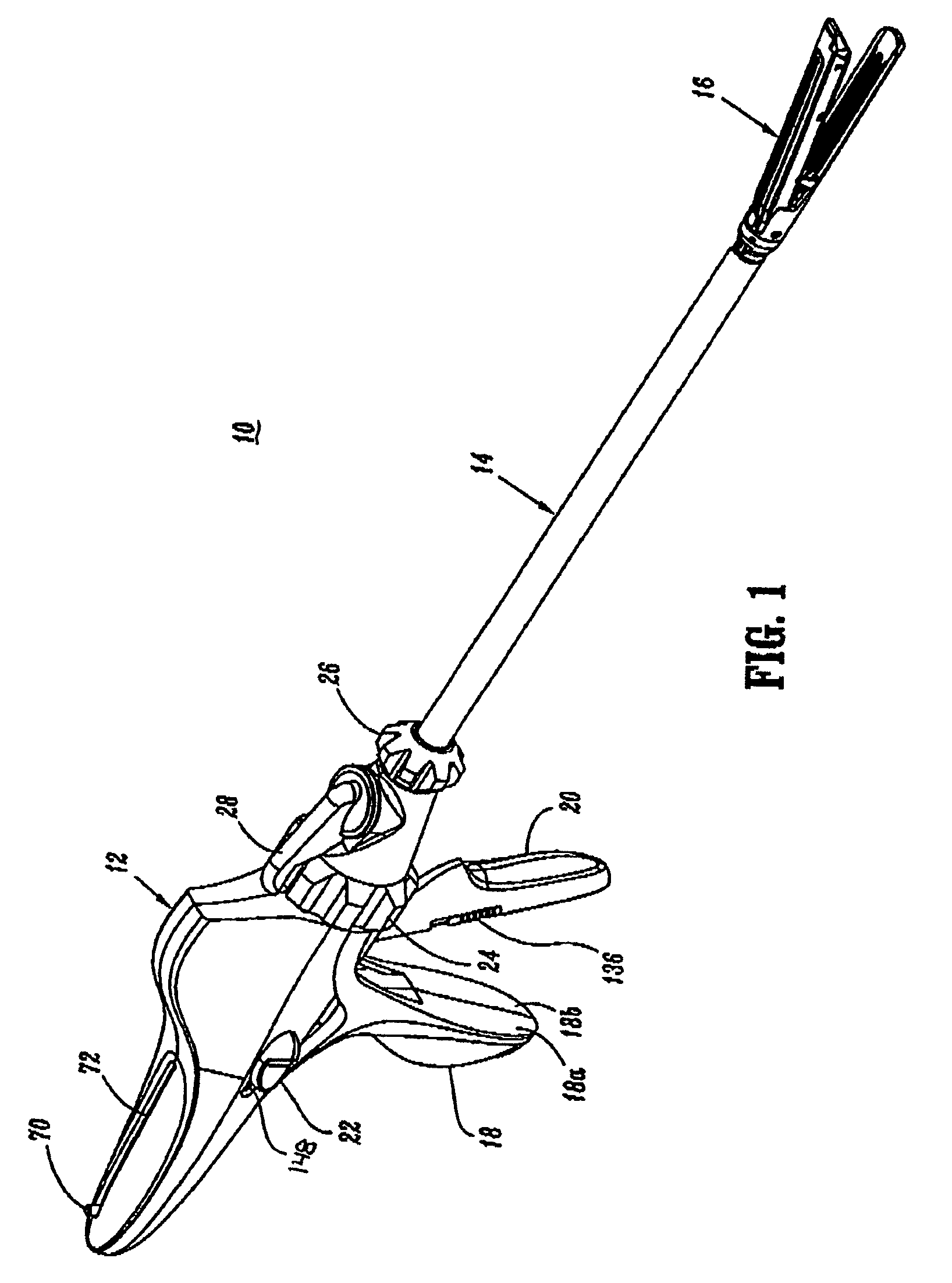
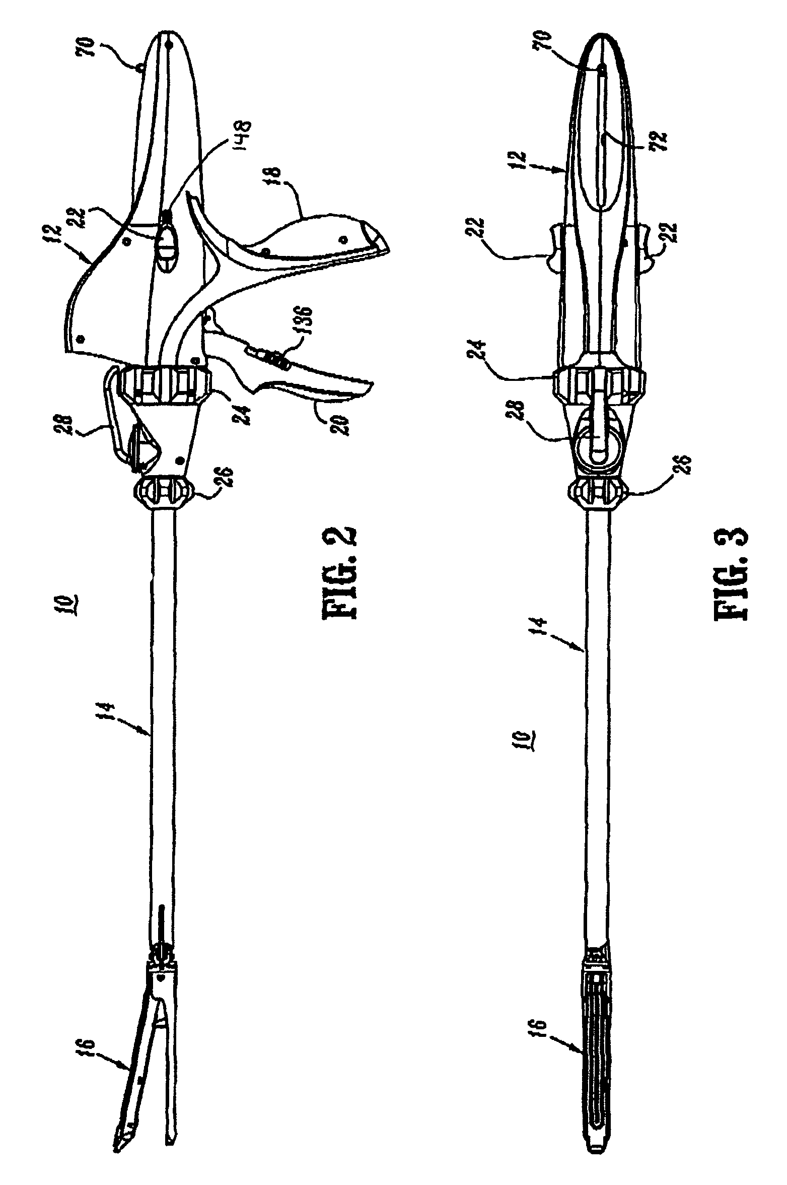
[0093]FIGS. 1-3 illustrate one embodiment of the presently disclosed surgical stapling device shown generally as 10. Briefly, surgical stapling device 10 includes a handle assembly 12, an endoscopic body portion 14 and a tool assembly 16. Handle assembly 12 includes a stationary handle portion 18 and a firing or operating trigger 20. A grasper button 22 is movably positioned on handle assembly 12 adjacent stationary handle portion 18. A body rotation knob 24 is rotatably supported adjacent a distal end of handle assembly 12 and a tool assembly rotation knob 26 is rotatably supported adjacent the distal end of rotation knob 18. Rotation knob 24 may be formed from molded half-sections 24a and 24b which are secured together using any known fastening...


PUM


Abstract

A surgical stapling device is disclosed which includes a handle assembly, an endoscopic body portion and a tool assembly. The tool assembly is rotatably and pivotally supported on a distal end of the endoscopic body portion. A tool assembly rotation mechanism is provided which includes a rotation knob, a substantially rigid tube and a flexible member interconnecting the rigid tube to the tool assembly. The substantially rigid tube translates rotation of the rotation knob to rotation of the flexible member and provides a channel for passage of other components of the surgical stapling device.

Description

CROSS-REFERENCE TO RELATED APPLICATIONS[0001]This application is a continuation of U.S. application Ser. No. 10 / 968,525 filed Oct. 18, 2004, which claims benefit of application No. 60 / 512,481 filed Oct. 17, 2003, and the disclosures of each of the above-identified applications are hereby incorporated by reference in their entirety.BACKGROUND[0002]1. Technical Field[0003]The present application relates to a surgical stapling device and, more particularly, to an endoscopic surgical stapling device having a tool assembly and an endoscopic body portion, wherein the tool assembly is rotatable independently of the endoscopic body portion.[0004]2. Background of Related Art[0005]Surgical devices having a tool assembly for grasping or clamping tissue between opposing jaw structure and then joining the tissue using surgical fasteners are well known in the art. In some such devices, a knife is provided to cut the tissue which has been joined by the fasteners. The fasteners are typically in the...

Claims


Application Information

Patent Timeline
Patent Type & Authority Patents(United States)
IPC IPC(8): A61B17/068A61B17/03A61B17/04A61B17/072A61B17/28A61L
CPCA61B17/07207A61B17/068A61B2017/07214A61B2017/07285A61B2017/2922A61B2017/2923A61B2017/2927A61B2017/2932A61B2017/2937A61B2017/2946A61B2017/2925
Inventor RACENET, DAVID C.STEARNS, RALPHROY, PHILIPBEARDSLEY, JOHN W.OLSON, LEE ANN
Owner COVIDIEN LP
Why Eureka
Try Eureka