
Method for inserting an intraocular lens

a technology of intraocular lens and eye, which is applied in the field of intraocular lens insertion, can solve the problems of various drawbacks of known implantation devices, and achieve the effects of slowing down the entry of intraocular lens, preventing further advancement of intraocular lens, and inhibiting the sudden release of mechanical energy

Inactive Publication Date: 2013-04-23
VISIOGEN
View PDF177 Cites 26 Cited by
  • Summary
  • Abstract
  • Description
  • Claims
  • Application Information

AI Technical Summary

Benefits of technology

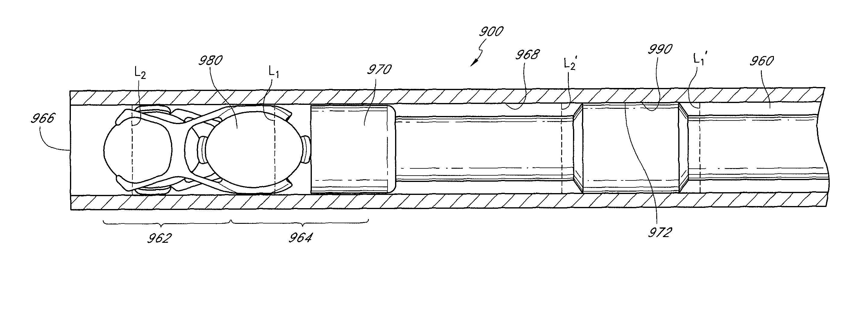
[0006]In some embodiments, as discussed further below, an increase from the first lens coefficient of friction to the second lens coefficient of friction can advantageously provide a tactile feedback to a user indicating that the lens is at or near the distal end of the lumen.
[0014]In some embodiments, a method for injecting an intraocular lens comprising multiple optics into an eye comprises providing an injector having the intraocular lens positioned in an injection lumen with at least one optic in front of another optic. The method can further include inserting a release control section of the injector into the eye such that substantially the entire release control section is in the anterior chamber of the eye. The method can also include advancing the intraocular lens to the release control section. In some embodiments, the method includes using the release control section to significantly retard further advancement of the intraocular lens into the eye. The release control section can inhibit sudden release of mechanical energy stored in the compacted intraocular lens and slow entry of the intraocular lens from the injector into the anterior chamber. Other embodiments are also disclosed.

Problems solved by technology

However, these known implantation devices suffer from various drawbacks, many of which are addressed by certain embodiments disclosed herein.

Method used


Image

  • Method for inserting an intraocular lens
  • Method for inserting an intraocular lens
  • Method for inserting an intraocular lens

Examples


Embodiment Construction

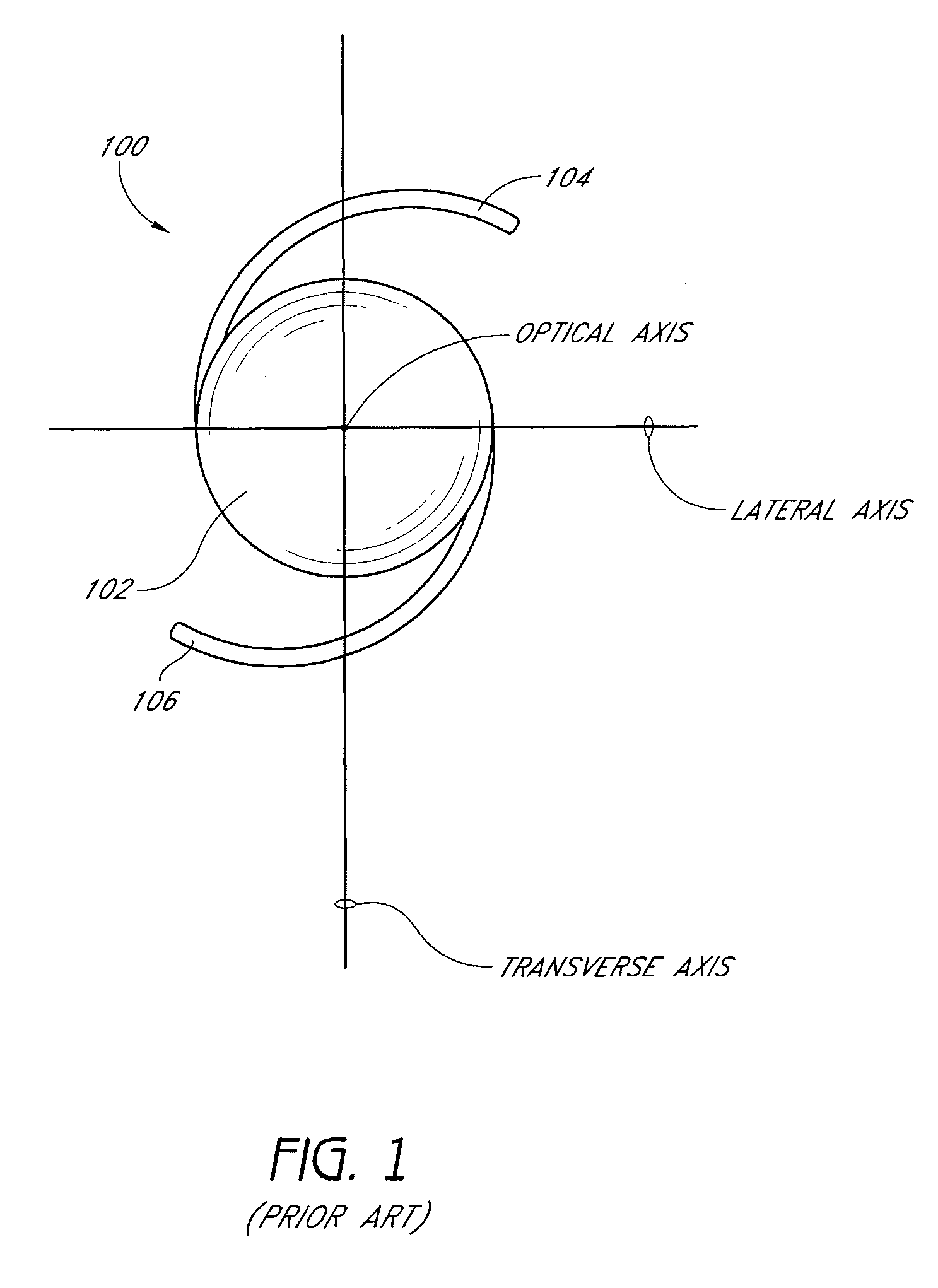
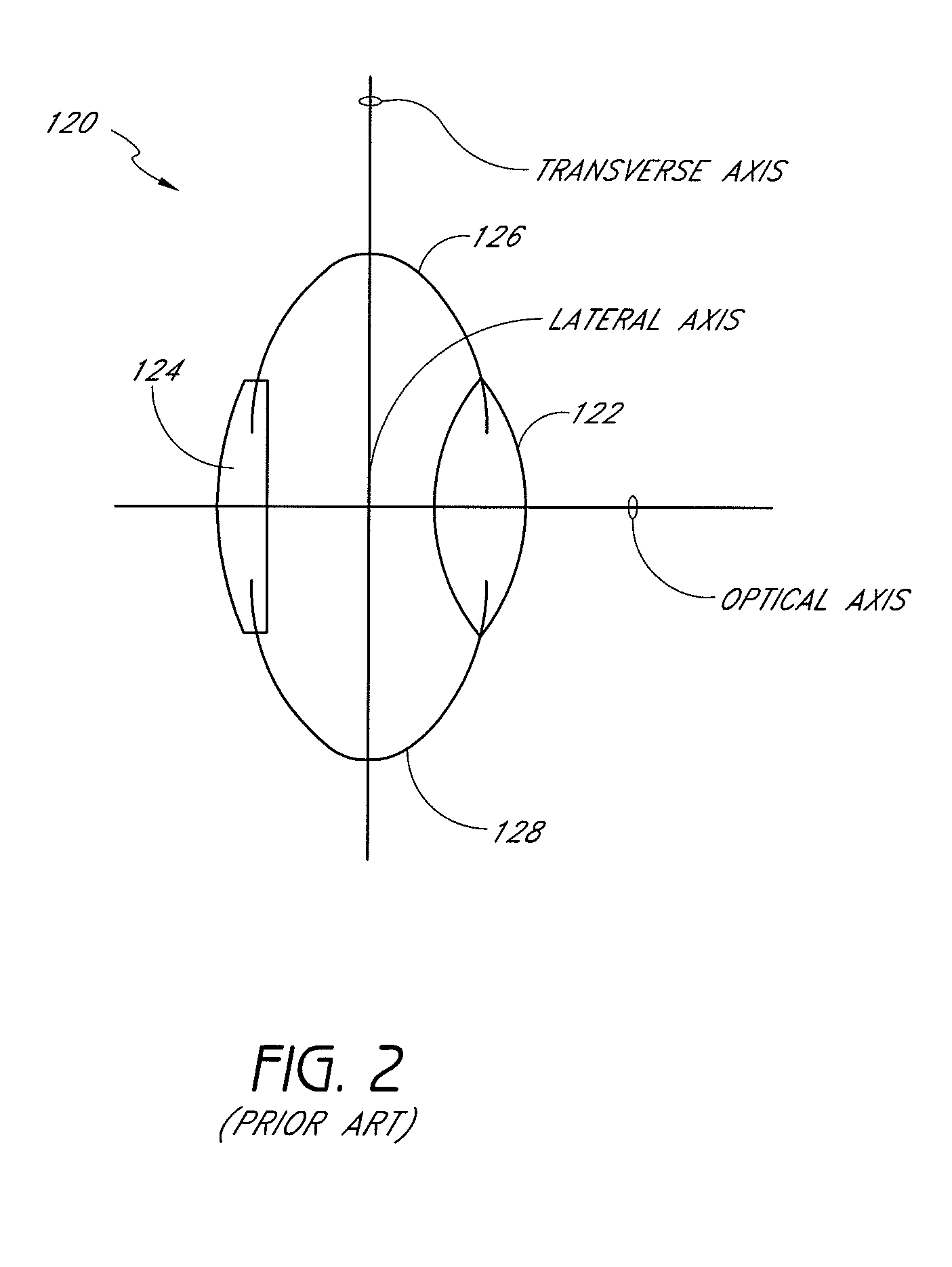
[0081]FIGS. 1 and 2 depict two known types of intraocular lenses (“IOLs”) which are suitable for implantation in a human or animal eye to replace or supplement the natural crystalline lens. An IOL may be implanted, for example, when the natural lens has developed cataracts or has lost elasticity to create a condition of presbyopia.

[0082]FIG. 1 is front view of a conventional single-lens IOL 100 comprising an optic 102 to which are connected two or more haptics 104, 106. The optic 102 typically has a refractive power which is selected to replace or adjust the optical performance of the natural lens. The haptics 104, 106 comprise spring-like members which fix the optic in an appropriate location (e.g., inside the ciliary capsule or between the cornea and iris). The IOL 100 has an optical axis generally orthogonal to and centered on the optic; accordingly, in FIG. 1 the optical axis is depicted as a point. In addition, the IOL 100 has a transverse axis orthogonal to the optical axis an...


PUM


Abstract

An injector for inserting an intraocular lens into an eye includes a lumen. The lumen can include a terminal portion at a distal end and a proximal portion juxtaposed with the terminal portion. An injector plunger can be disposed within the lumen for generating a driving force on the intraocular lens. The injector can include a lens frictional force that has a first value when the lens is at a first location within the proximal portion and a second value when the lens is at a second location within the terminal portion. The first value can be smaller than the second value. In some embodiments, the lens frictional force increases abruptly from the first value to the second value as the lens approaches the distal end of the lumen.

Description

BACKGROUND OF THE INVENTIONS[0001]1. Field of the Inventions[0002]Various embodiments disclosed herein pertain to insertion of intraocular lenses into the eye of a patient, as well as methods and devices for preparing an intraocular lens for insertion, and for achieving the insertion itself.[0003]2. Description of the Related Art[0004]Artificial intraocular lenses are often implanted to replace or supplement the natural crystalline lens. Such a lens may be implanted where the natural lens has developed cataracts or has lost elasticity to create a condition of presbyopia. Implantation devices have been developed to roll or fold an intraocular lens, and / or assist in implanting a rolled or folded lens through a small incision in the patient's eye. However, these known implantation devices suffer from various drawbacks, many of which are addressed by certain embodiments disclosed herein.SUMMARY OF THE INVENTIONS[0005]In certain embodiments, an injector for inserting an intraocular lens ...

Claims


Application Information

Patent Timeline
Patent Type & Authority Patents(United States)
IPC IPC(8): A61F2/16
CPCA61F2/1648A61F2/1678A61F2/1675A61F2/1629A61F2250/0021A61F2250/0025A61F2002/1683
Inventor TSAI, GEORGENGUYEN, TUAN ANHNGUYEN, PHU H.EVANS, SCOTT
Owner VISIOGEN
Learn More