
Adjusting device for tightening or loosing laces and straps

a technology of adjusting device and laces, which is applied in the direction of snap fasteners, buckles, shoe lace fastenings, etc., can solve the problems of easy breakage of the releasable lock mechanism, user cannot directly rotate the knob to wind and unwind the lace,

Active Publication Date: 2013-05-07
CHEN CHIN CHU
View PDF34 Cites 102 Cited by
  • Summary
  • Abstract
  • Description
  • Claims
  • Application Information

AI Technical Summary

Problems solved by technology

1. The user needs to move the knob to one engaged position or one disengaged position at first, then the user can rotate the knob to wind or unwind the lace and the strap. Therefore, the user cannot directly rotate the knob to wind and unwind the lace and the strap.
2. The releasable lock mechanism might be broken easily after the knob is moving up and down frequently, and the knob might unexpectedly depart from the tightening device.

Method used


Image

  • Adjusting device for tightening or loosing laces and straps
  • Adjusting device for tightening or loosing laces and straps
  • Adjusting device for tightening or loosing laces and straps

Examples


Embodiment Construction

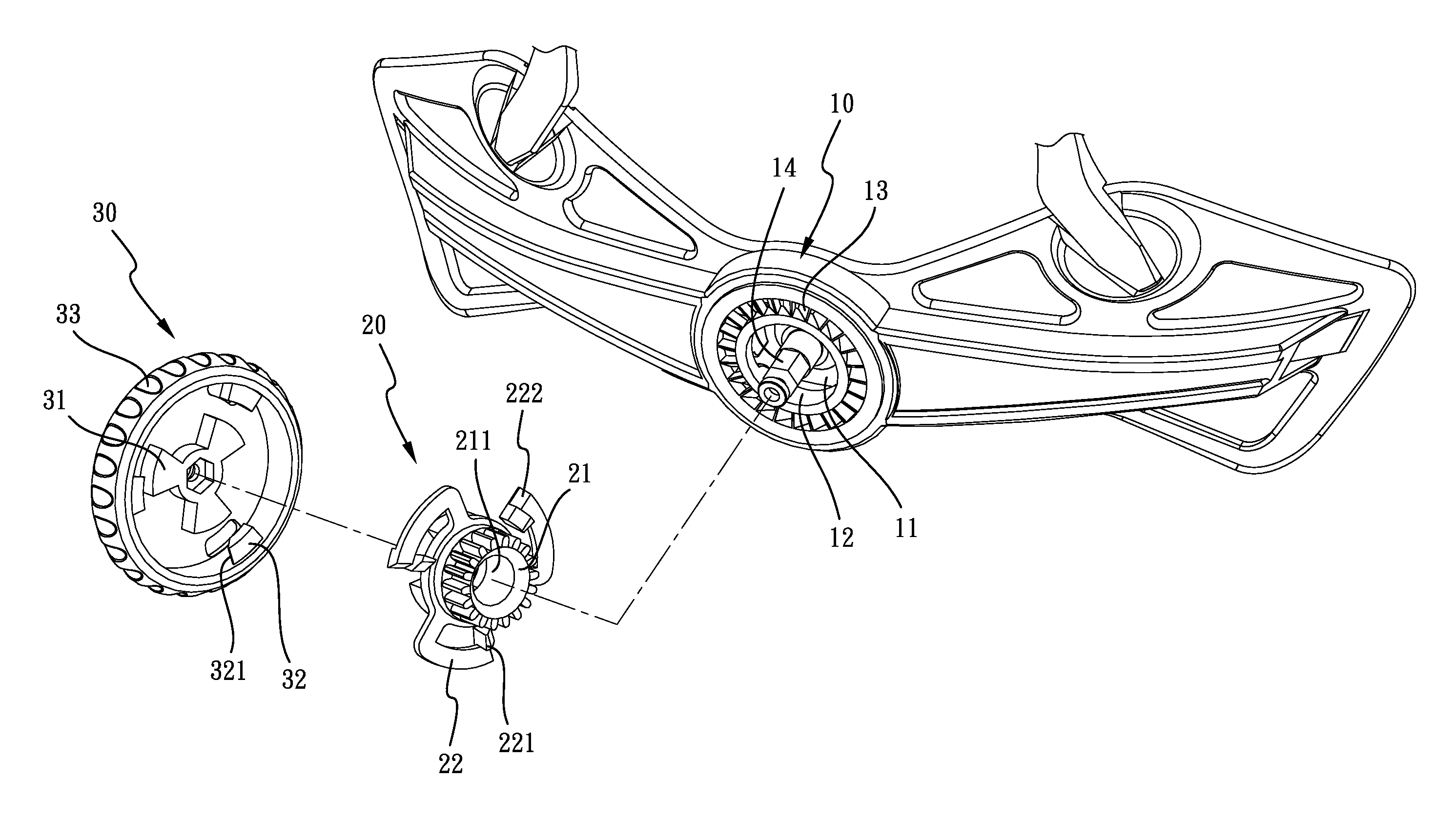
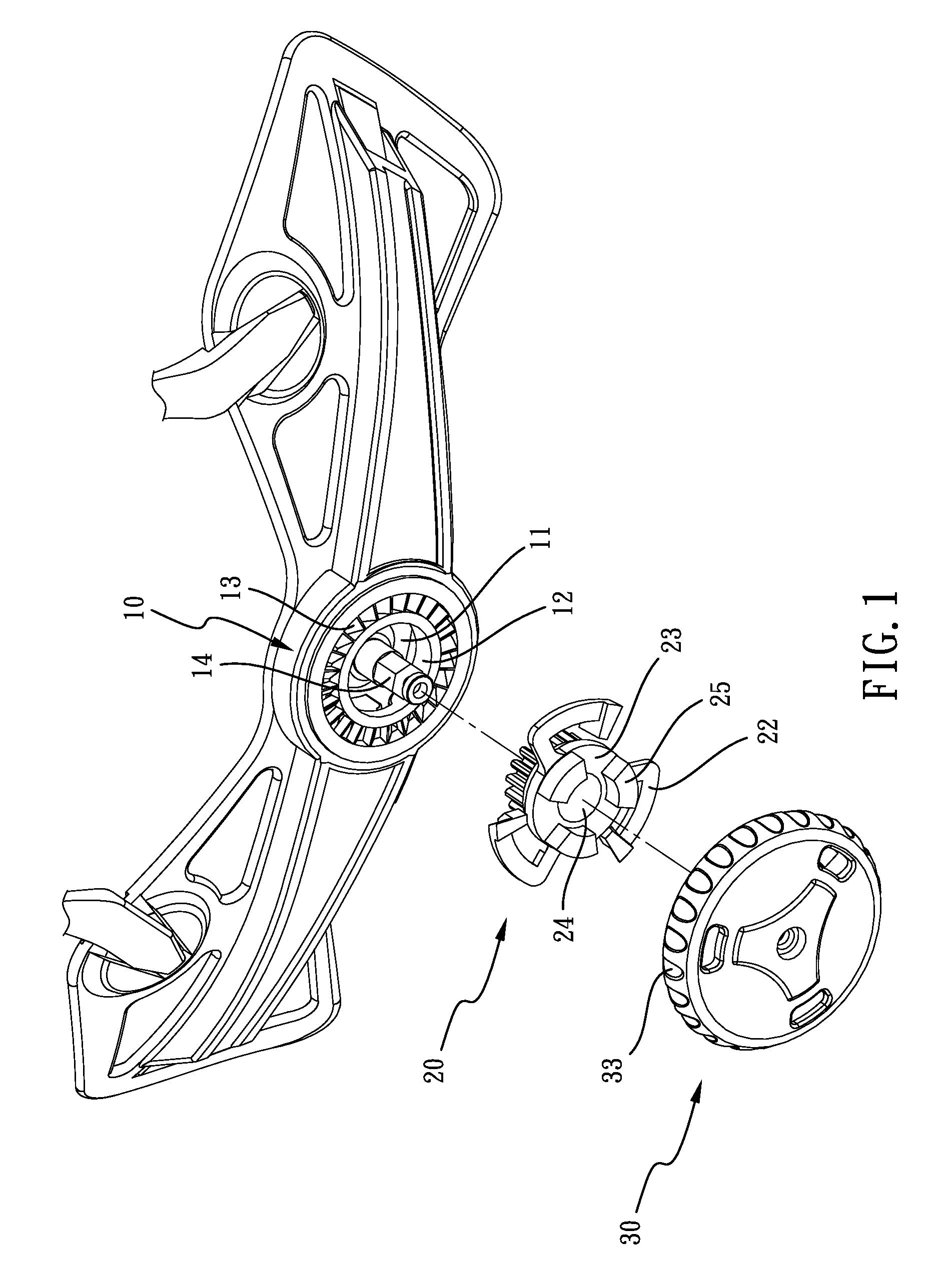
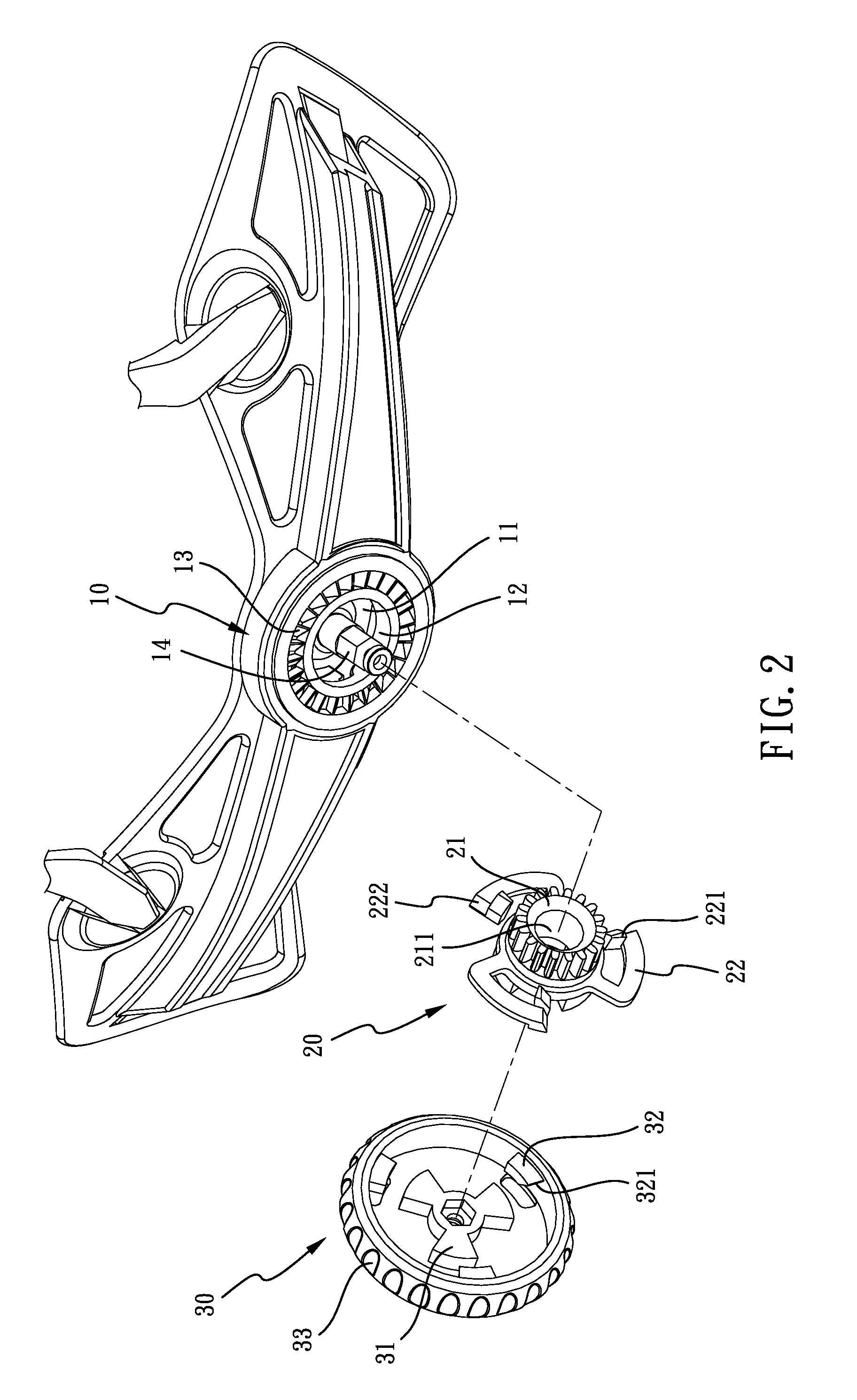
[0024]Referring to the drawings to FIGS. 1-9, an adjusting device for tightening or loosing laces and straps in accordance with the present invention comprises a base 10, an actuating member 20 and a knob 30. An axis 14 is deposited at the center of the base 10. The base 10 has a receiving space 11 defined therein for receiving a flexible strap 40. A through hole 12 is opened on the base 10 and is communicated with the receiving space 11. A plurality of unidirectional inclined planes 13 is deposited circularly around the through hole 12 on the base 10.

[0025]The actuating member 20 has a gear wheel 21. The gear wheel 21 has a connecting hole 211 at the center. The gear wheel 21 is passed through the through hole 12 and drives the flexible strap 40 to move back and forth in the receiving space 11. The actuating member 20 has a plurality of driving ribs 25 thereon. An assembling space 23 is formed from one driving rib 25 to another driving rib 25 for connecting to the knob 30. An openi...


PUM


Abstract

An adjusting device for tightening or loosing laces and straps includes a base, an actuating member and a knob. When a user rotates the knob clockwise, the adjusting device is tightening a flexible strap of the clothing or a lace of the footwear. However, when a user rotates the knob counterclockwise, the adjusting device is loosing a flexible strap of the clothing or a lace of the footwear. The knob never moves up and down along the axis during the operation for tightening or loosing the flexible strap or the lace.

Description

BACKGROUND OF THE INVENTION[0001]1. Field of the Invention[0002]The present invention relates to a tightening device applied in footwear or clothing, and more particularly to an adjusting device for tightening or loosing laces and straps.[0003]2. Description of Related Art[0004]Referring to U.S. Pat. No. 6,289,558, a conventional tightening device for laces includes a knob, a plurality of gear wheels with ratchet sections, a reel and a releasable lock mechanism. The reel is rotatable for receiving the lace. The knob is connected to the gear wheels and the knob is moveable along an axis of rotation between an engaged position and a disengaged position relative to the releasable lock mechanism. The gear wheel drives the reel to wind or unwind the lace. When a user rotates the knob in the said first direction, the reel is also driven by the gear wheels to rotate in the first direction for winding the lace. In addition, the releasable lock mechanism prevents rotation of the reel in the ...

Claims


Application Information

Patent Timeline
Patent Type & Authority Patents(United States)
IPC IPC(8): A43C11/00B65H75/48A43C7/00
CPCA43C11/165Y10T24/2183Y10T24/3724A42B3/145
Inventor CHEN, CHIN-CHU
Owner CHEN CHIN CHU
Learn More