Support structures on roofs

a technology for supporting structures and roofs, applied in roof drainage, girders, skylights/domes, etc., can solve the problems of restricting the relative movement of roof panels and curbs, reducing the number of incidents of water leakage, and all known conventional structures have a tendency to leak water

Active Publication Date: 2013-05-14
T&M INVENTIONS
View PDF53 Cites 30 Cited by
  • Summary
  • Abstract
  • Description
  • Claims
  • Application Information

AI Technical Summary

Problems solved by technology

The retrofitting of such curb systems into an existing roof structure is problematic in that all known conventional structures have a tendency to leak water when subjected to rain due to installation details and complexities which are affected by installation techniques or workmanship.
These multiple curbs, each around a separate roof aperture, create multiple opportunities for water to enter the interior of the building, due to multiple apertures and the widths of the curbs, thus the cuts through the multiple ribs, as well as presenting the challenge to effectively seal the roof at the high ends of such curbs.
The traditional curb constructions and methods of attachment in most cases thus require that a complicated support structure be installed below the roof panel and inside the building enclosure, which can restrict the relative movement of the roof panels and the curb, as associated with thermal expansion and contraction of the overlying metal roof due to temperature changes and the like.
None of the prior approaches have been able to provide an installation system for multiple skylights which accomplishes the goals of economy and simplicity of installation and which works equally well for new buildings and as retrofits in existing buildings.

Method used


Image

  • Support structures on roofs
  • Support structures on roofs
  • Support structures on roofs

Examples


Embodiment Construction

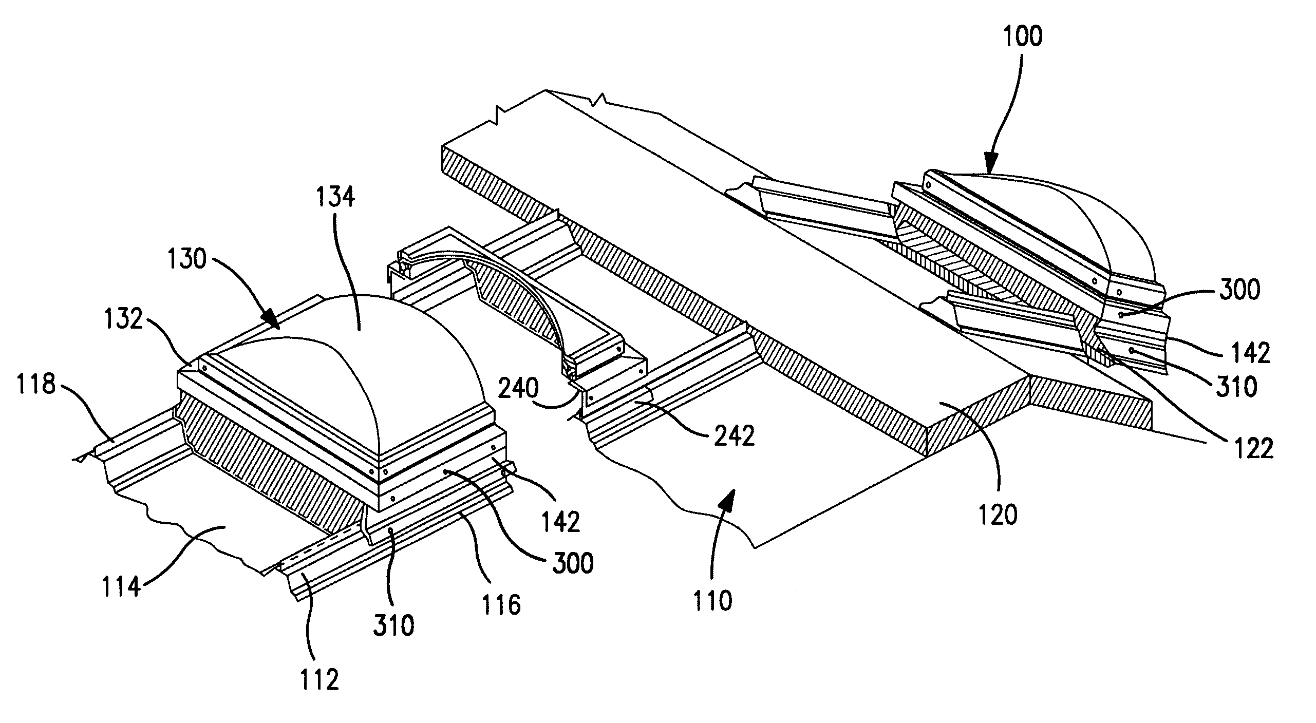
[0057]The products and methods of the present invention provide a load support structure, optionally a rail and closure structure for use in installing various exterior roof loads, as well as structures which close off apertures in metal roofs. For purposes of simplicity, “roof penetrating structures” and “skylights” will be used interchangeably to mean various forms of roof structures installed on the upper surface of the roof and closing off roof apertures while providing for passage of light and / or ventilation, air handling, vents, air intake, air or other gaseous exchange to and / or from the interior of the building. In the case of roof ventilation, examples include simple ventilation openings, such as for roof fans, and smoke vents, which are used to allow the escape of smoke through the roof during fires. In the case of exterior loads on the roof, there can be mentioned, without limitation, such loads as air conditioners, air handlers, solar panels and other equipment related b...


PUM


Abstract

This invention provides support structures on roofs. Such support structure can be used to support a roof load, or a closure structure which closes an aperture in the roof, thus to provide access to the interior of a building through an aperture in the roof. The support structure can support a skylight to provide natural day-lighting, or a smoke vent, or a variety of other loads optionally relating to matter or energy communication between the inside and outside of the building. The support structure includes rails adapted to be supported by adjacent rib elevations on opposite sides of a flat of a roof panel, elevated above the water line of the panel flat. Where the support structure surrounds an aperture, a diverter seals a cut away portion of the rib structure and diverts water through the rib structure and laterally away from the rail and closure structure.

Description

REFERENCE TO RELATED APPLICATIONS[0001]This application claims the priority benefit of U.S. Provisional Patent Application No. 61 / 102,333, filed Oct. 2, 2008, and is a Continuation-In-Part of U.S. Non-Provisional patent application Ser. No. 12 / 572,176, filed Oct. 1, 2009, and is a Continuation-In-Part of U.S. Non-Provisional patent application Ser. No. 12 / 932,892, filed Mar. 8, 2011, the complete disclosures of which are incorporated by reference herein, in their entireties.BACKGROUND OF THE INVENTION[0002]Various systems are known for supporting loads on roofs, and for installing skylights and / or smoke vents into roofs.[0003]The most commonly used skylighting systems are those which incorporate translucent or transparent closure members, also referred to herein as lenses, into a framework which penetrates the roof support structure and may be supported from within the building, with the result that the skylight closure member transmits ambient daylight into the building.[0004]In th...

Claims


Application Information

Patent Timeline
Patent Type & Authority Patents(United States)
IPC IPC(8): E04B7/18E04B7/04E06B3/26E04B7/02
CPCE04D3/364E04D3/365E04D13/0315E04D13/031E04D13/00E04D13/03E04D13/04E04B1/6803
Inventor MCLAIN, MICHAEL J.PENDLEY, TIMOTHY
Owner T&M INVENTIONS
Why Eureka
Try Eureka