Bulb changing system

a technology of bulb and switch, which is applied in the direction of electrical equipment, installation/removing discharge tubes/lamp auxilary devices, etc., can solve the problems of difficult and dangerous to do, difficult to access the bulb, and burnout and need to be replaced

Active Publication Date: 2013-06-04
ELLIS JAMES CHILDS
View PDF24 Cites 3 Cited by
  • Summary
  • Abstract
  • Description
  • Claims
  • Application Information

AI Technical Summary

Problems solved by technology

While the bulbs are designed to last for years, eventually they burn out and need to be replaced.
Chandeliers are generally installed in locations where it is difficult to access the bulbs, even by using ladders.
Where the bulbs are readily accessed via ladder, it can be difficult and dangerous to do so.

Method used


Image

  • Bulb changing system
  • Bulb changing system
  • Bulb changing system

Examples


Embodiment Construction

[0017]The present invention can be understood more readily by reference to the following detailed description, examples, drawing, and claims, and their previous and following description. However, before the present devices, systems, and / or methods are disclosed and described, it is to be understood that this invention is not limited to the specific devices, systems, and / or methods disclosed unless otherwise specified, as such can, of course, vary. It is also to be understood that the terminology used herein is for the purpose of describing particular aspects only and is not intended to be limiting.

[0018]The following description of the invention is provided as an enabling teaching of the invention in its best, currently known embodiment. To this end, those skilled in the relevant art will recognize and appreciate that many changes can be made to the various aspects of the invention described herein, while still obtaining the beneficial results of the present invention. It will also...


PUM


Abstract

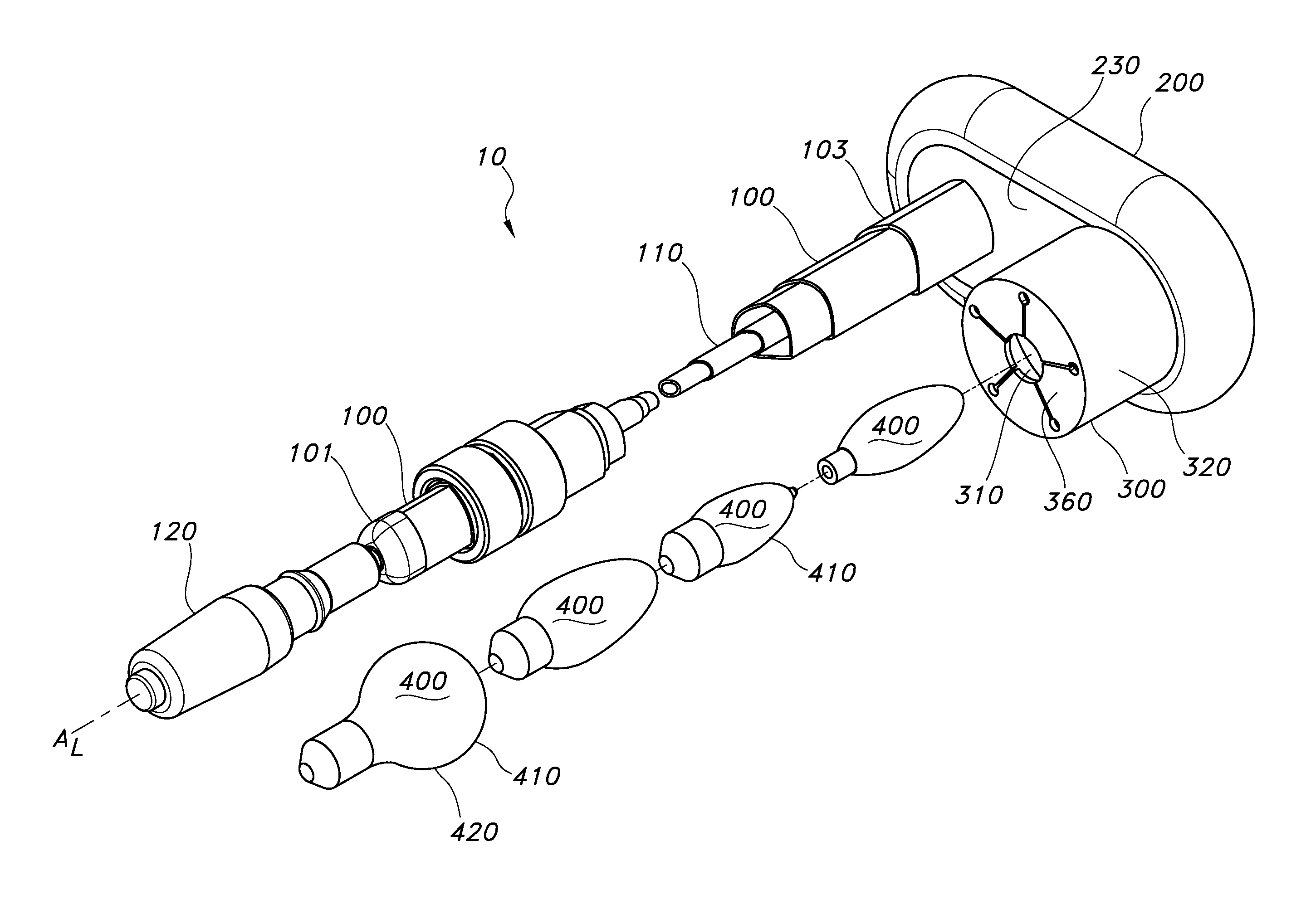
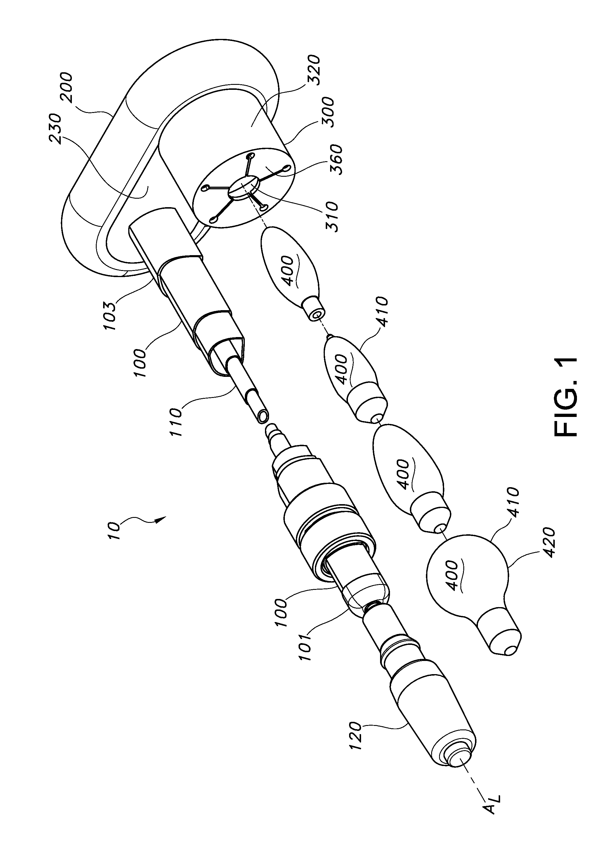
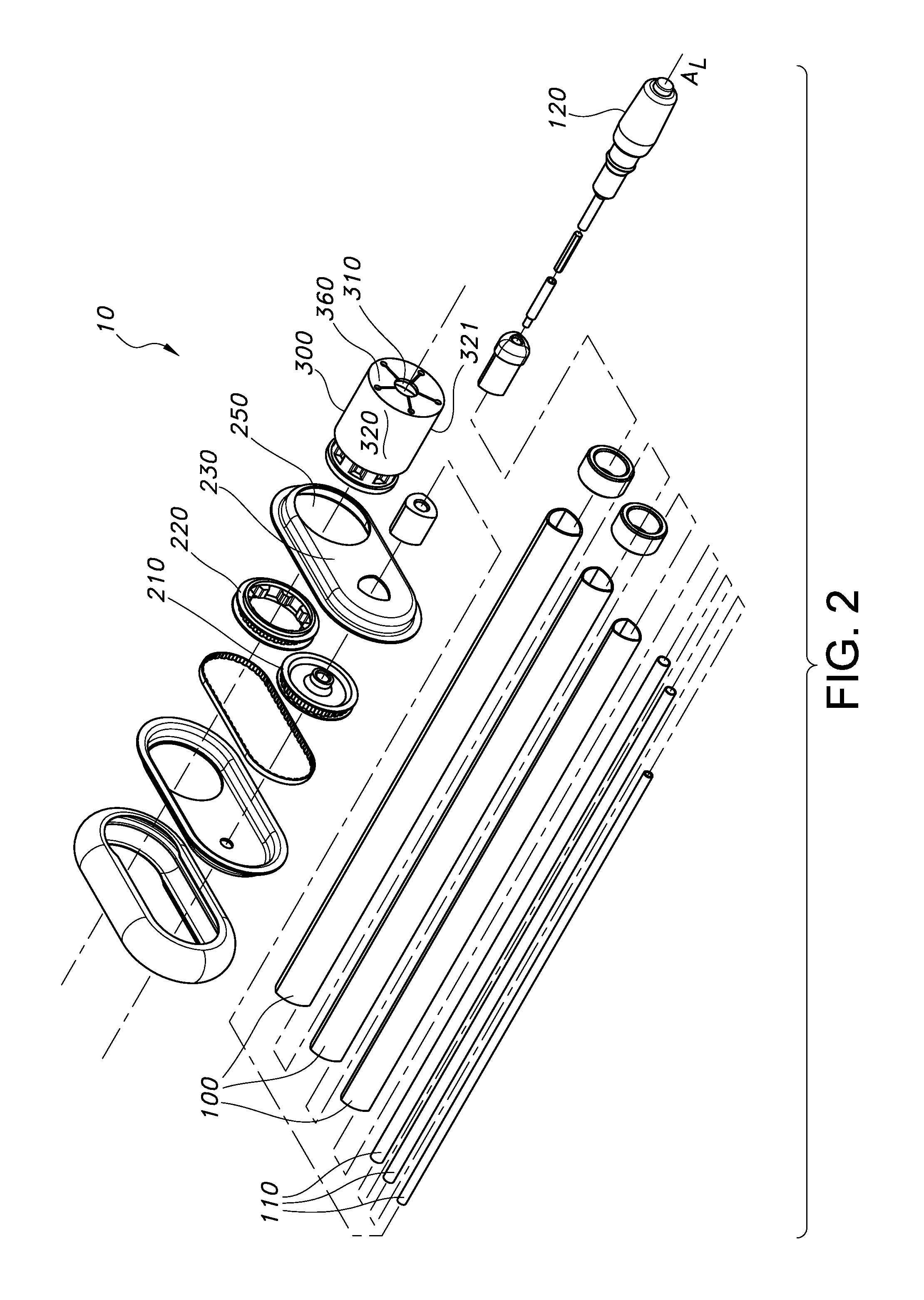
A bulb changing system for elevated light bulbs is presented. The system has an elongate tube, a drive shaft with a drive handle, a drive gear, a driven gear, and a light receptacle configured to engage an exterior portion of the light bulb. In one aspect, the drive housing houses the drive gear and the driven gear therein a drive cavity and rotation of the drive handle causes the drive gear to rotate substantially along the longitudinal axis of the elongate tube, which in turn, causes the driven gear to rotate, which in turn, causes the light receptacle to rotate. As such, the light bulb is rotated into or out of engagement with a socket, depending upon the direction of rotation.

Description

FIELD OF THE INVENTION[0001]Presented herein is a bulb changing system. More specifically, a bulb changing system primarily used to change light bulbs in difficult to reach areas.BACKGROUND OF THE INVENTION[0002]In the chandelier industry, lighting systems comprise a plurality of light bulbs. While the bulbs are designed to last for years, eventually they burn out and need to be replaced. Chandeliers are generally installed in locations where it is difficult to access the bulbs, even by using ladders. Where the bulbs are readily accessed via ladder, it can be difficult and dangerous to do so.[0003]What is needed in the industry is a system for changing bulbs in chandeliers that is both safe and easy.SUMMARY[0004]Presented herein is a bulb changing system comprising an elongate tube, a drive shaft with a drive handle, a drive gear, a driven gear, and a light receptacle configured to engage an exterior portion of the light bulb.[0005]The drive housing houses the drive gear and the dri...

Claims


Application Information

Patent Timeline
Patent Type & Authority Patents(United States)
IPC IPC(8): H01K3/32
CPCH01J9/003H01K3/32
Inventor ELLIS, JAMES CHILDS
Owner ELLIS JAMES CHILDS
Why Eureka
Try Eureka