Unlock instant, AI-driven research and patent intelligence for your innovation.

Fuel injector

a fuel injector and fuel technology, applied in the direction of fuel injection apparatus, fuel feed system, engine components, etc., can solve the problems of unmetered fuel being dispensed, increased fuel pressure, and fuel being dispensed that is not properly atomized

Active Publication Date: 2013-06-04
DELPHI TECH IP LTD
View PDF6 Cites 4 Cited by
  • Summary
  • Abstract
  • Description
  • Claims
  • Application Information

AI Technical Summary

Benefits of technology

The invention is a fuel injector with a housing stop that absorbs kinetic energy from a sliding armature when the fuel injector is turned off. The housing stop prevents the sliding armature from hitting the pintle stop and causing damage. This feature improves the reliability and durability of the fuel injector.

Problems solved by technology

However, some direct injection fuel systems have increased fuel pressures to a level where it becomes difficult to provide a fuel injector that has the same physical outline or package size as injectors designed for lower fuel pressure levels, and is able to reliably ‘dead lift’ the pintle / ball assembly at the higher fuel pressure levels.
However, the additional mass of this armature undesirably increases the impact force of the pintle / ball assembly on the nozzle seat when the fuel injector is turned OFF, which may lead to the ball bouncing back off the nozzle seat, thereby resulting in unmetered fuel being dispensed, or fuel being dispensed that is not properly atomized.
The increased impact force may also lead to undesirable noise and / or reduced injector life.

Method used


Image

  • Fuel injector
  • Fuel injector
  • Fuel injector

Examples


Embodiment Construction

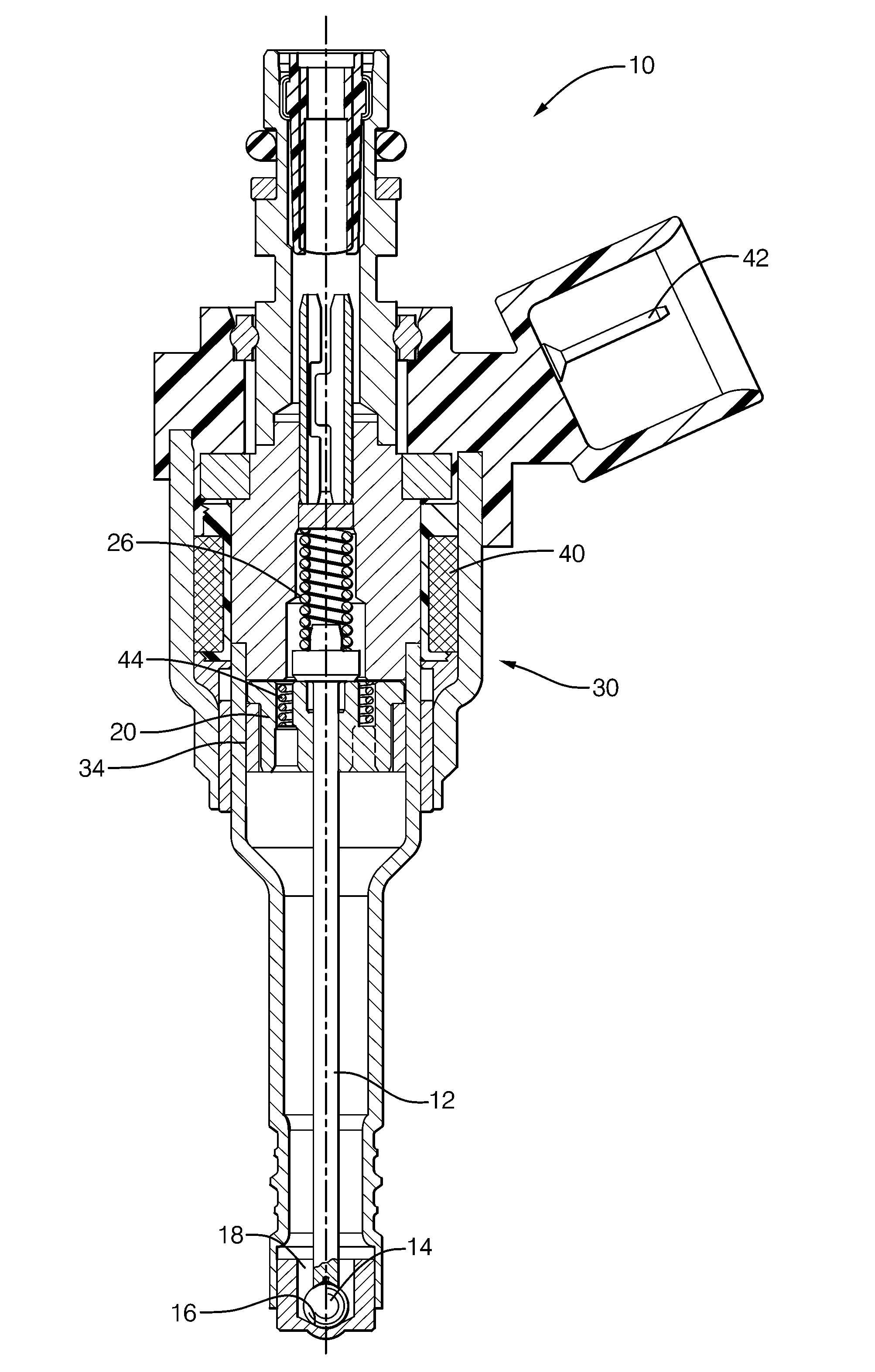
[0011]In accordance with an embodiment of a fuel injector for an internal combustion engine, FIGS. 1-2 illustrate a fuel injector 10. In general, the injector 10 has a pintle 12 that may include a ball 14 or other feature configured to cooperate with a nozzle seat 16 to regulate the flow of fuel in cavity 18, hereafter fuel 18, to be dispensed by the injector 10. FIG. 2A shows the pintle 12 after moving into a closed position that positions the ball 14 in contact with the nozzle seat 16 to prevent fuel 18 from flowing out of injector 10. FIG. 2B shows the pintle 12 after moving into an open position so the ball 14 can be apart from the nozzle seat 16 to allow fuel 18 to be dispensed by the fuel injector 10.

[0012]The injector 10 may also include a sliding armature 20 movable between a first position against a housing stop 22 as illustrated in FIG. 2A, and a second position against an armature stop 24 as illustrated in FIG. 2B. As will be explained in more detail later, the sliding ar...


PUM


Abstract

A fuel injector that includes a sliding armature, decoupled armature, or flying armature movable between a pintle stop and a housing stop. Flying armatures are generally used to increase the total force applied to the pintle stop for lifting the pintle off a nozzle seat to open the fuel injector. When the fuel injector is turned off, a housing stop is arranged to absorb kinetic energy present in the flying armature so that the kinetic energy is not imparted to the nozzle seat.

Description

TECHNICAL FIELD OF INVENTION[0001]The invention generally relates to a fuel injector, and more particularly relates to reducing the occurrence of pintle bounce back when the fuel injector is turned off to stop fuel from flowing from the fuel injector.BACKGROUND OF INVENTION[0002]Many electro-magnetic type fuel injectors are configured such that when a current is applied to a coil winding within the fuel injector, a magnetic field is generated that urges the pintle / ball assembly away from the nozzle seat and thereby turns the injector ON. In general, the amount of force needed to lift a pintle / ball assembly from the injector OFF or closed position to the injector ON or open position is proportional to a pintle return spring force plus a fuel pressure of the fuel present in the injector. However, some direct injection fuel systems have increased fuel pressures to a level where it becomes difficult to provide a fuel injector that has the same physical outline or package size as injecto...

Claims


Application Information

Patent Timeline
Patent Type & Authority Patents(United States)
IPC IPC(8): B05B1/30
CPCF02M51/0685F02M63/0075F02M2200/306
Inventor PERRY, ROBERT B.SALEMI, MICHAEL RAYMONDALLEN, KEVIN J.KEEGAN, KEVIN RICHARD
Owner DELPHI TECH IP LTD