
Continuous variable aperture for forward looking infrared cameras based on adjustable blades

a technology of infrared cameras and adjustable blades, which is applied in the field of infrared cameras, can solve the problems of degrading the image, and affecting the image quality of the image,

Active Publication Date: 2013-06-11
OPTO KNOWLEDGE SYST
View PDF113 Cites 11 Cited by
  • Summary
  • Abstract
  • Description
  • Claims
  • Application Information

AI Technical Summary

Benefits of technology

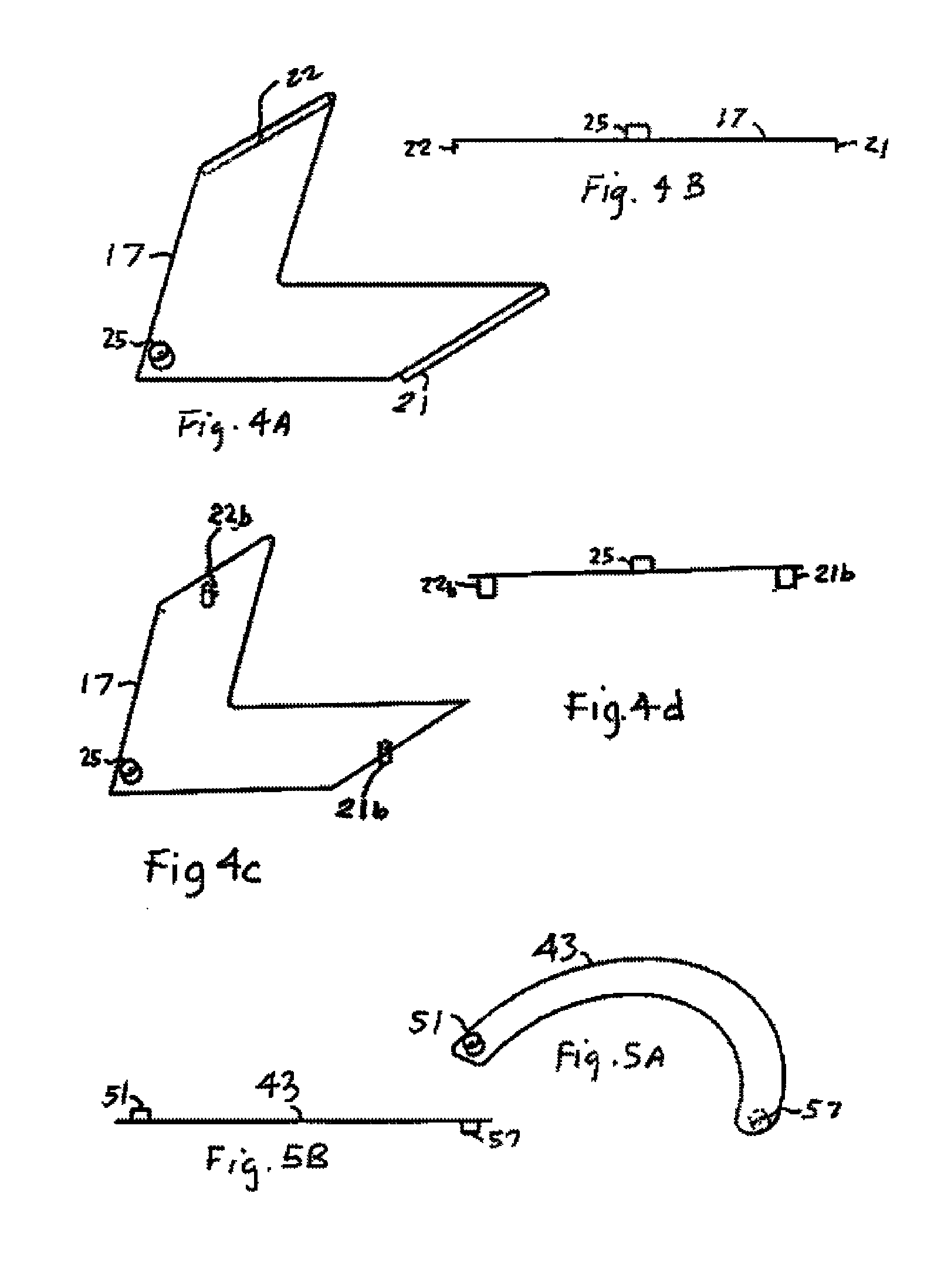
The invention is a non-circular adjustable continuous aperture for an infra-red camera. The aperture is formed using two L-shaped blades that move in a diagonally opposite relationship to each other. By shifting the blades in equal amounts along the diagonals, the size of the formed aperture can be adjusted without changing the aspect ratio of the sides. An additional set of four C-shaped blades can also be added to form a rounded shape at the corners of the aperture. The invention allows for precise adjustments and stabilization of the aperture size, making it easier to use with other optical elements.

Problems solved by technology

Thus parts of the camera or the foreoptics can be a source of unwanted infrared radiation if protective measures are not undertaken.
The cold stop aperture may then be too large or too small.
If it is too small, the aperture blocks some of the desired radiation from entering the detector, causing vignetting.
If the aperture is too large, it admits too much of the unwanted radiation, which degrades the image.
Such mechanisms, however, are not amenable to produce continuous variable rectangular, square or racetrack shaped apertures.
The problem with the foregoing apertures that produce non-circular openings is that they provide limited discrete aperture sizes, typically limited to two aperture sizes in the requisite geometry or shape, but are not continuous.
Because the shapes assumed by the aperture in the in-between positions varies widely and differs from the desired shape that matches the aperture shape defined by the optics, the foregoing designs for the non-circular apertures are unacceptable.

Method used


Image

  • Continuous variable aperture for forward looking infrared cameras based on adjustable blades
  • Continuous variable aperture for forward looking infrared cameras based on adjustable blades
  • Continuous variable aperture for forward looking infrared cameras based on adjustable blades

Examples


Embodiment Construction

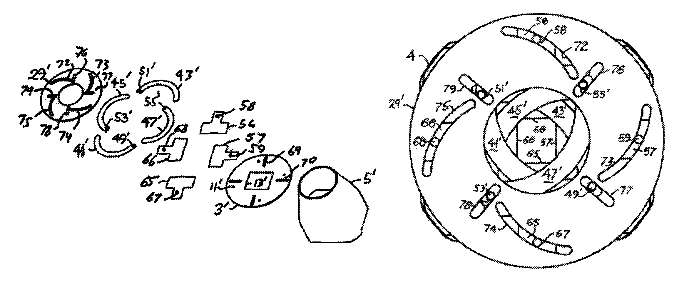
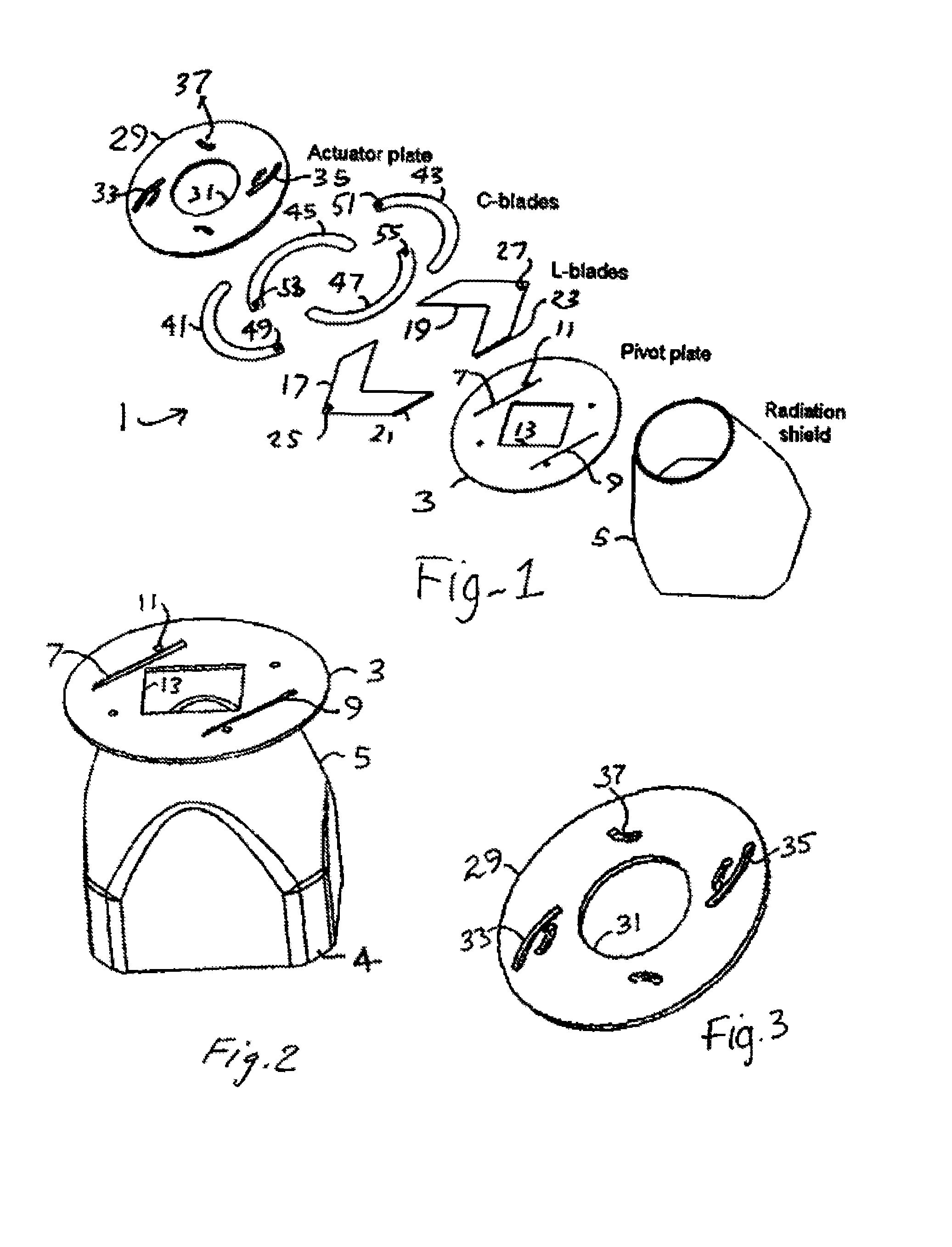
[0034]Reference is made to the exploded view of the aperture assembly 1 presented in FIG. 1. The assembly includes a pivot plate 3, also herein sometimes referred to as the base plate, mounted on top of the radiation shield 5, a hollow frusto-conical-like shaped metal member. The pivot plate contains two straight slots, 7 and 9 and four pivot holes 11, only one of which is numbered, and a central aperture 13. Those slots are cut or otherwise formed parallel to the diagonal, not illustrated, of the center square or rectangular aperture 13 in pivot plate 3. An actuator plate 29 contains a central circular shaped opening or passage 31 therethrough, a circular outer periphery that is concentric with passage 31, two long curved slots 33 and 35 located on diametrically opposite sides of passage 31 and is relatively thin and flat. Actuator 29 is to be mounted in a camera, not illustrated, with structure that permits the user, directly or indirectly, to rotate the actuator. In the assembled...


PUM


Abstract

A continuous variable non-circular aperture for an infra-red camera is formed by a plurality of positionable metal blades arranged to define there between an aperture of non-circular shape. A rotatable actuator plate positions the blades. Actuator rotation in one direction moves the metal blades to increase the size of the non-circular aperture without changing the non-circular shape of the aperture and vice-versa when the actuator plate is rotated in the opposite direction also maintaining the non-circular aperture shape. A preferred non-circular shape for a continuous variable aperture now possible is a rectangle; another is configured as a racetrack.

Description

CROSS-REFERENCE TO RELATED APPLICATIONS[0001]This patent application is a divisional application of and claims priority to U.S. patent application Ser. No. 12 / 006,428, filed Dec. 31, 2007, now U.S. Pat. No. 8,164,813, which claims the benefit of U.S. Provisional Patent Application No. 60 / 934,869, filed Jun. 16, 2007 entitled “NON-CIRCULAR CONTINUOUS VARIABLE APERTURE FOR FORWARD LOOKING INFRARED CAMERAS”. The entire content of the before-mentioned patent applications is incorporated by reference as part of the disclosure of this application.REFERENCE TO OTHER PATENTS & APPLICATIONS[0002]This application also makes reference to the following patents or published applications: U.S. Pat. No. 7,157,706, granted Jan. 2, 2007 to N. Gat, and application Ser. No. 11 / 273,919, filed Nov. 14, 2005, published Nov. 16, 2006 as Application no. US-2006-0255275-A1 to Garman et al.FIELD OF THE INVENTION[0003]This invention relates to infrared cameras of the type that contain either a continuous vari...

Claims


Application Information

Patent Timeline
Patent Type & Authority Patents(United States)
IPC IPC(8): G02B26/02
CPCG02B5/005G03B9/06G03B9/36
Inventor GAT, NAHUMZHANG, JINGYI
Owner OPTO KNOWLEDGE SYST
Learn More