Wall contact caliper instruments for use in a drill string

a technology for calipers and drill strings, which is applied in the direction of mechanical diameter measurement, survey, borehole/well accessories, etc., and can solve problems such as undesirable calipers or failure to function properly

Inactive Publication Date: 2013-07-16
SCHLUMBERGER TECH CORP
View PDF30 Cites 32 Cited by
  • Summary
  • Abstract
  • Description
  • Claims
  • Application Information

AI Technical Summary

Problems solved by technology

There are circumstances in which such calipers are undesirable or fail to function properly, e.g., drilling fluid having entrained gas.

Method used


Image

  • Wall contact caliper instruments for use in a drill string
  • Wall contact caliper instruments for use in a drill string
  • Wall contact caliper instruments for use in a drill string

Examples


Embodiment Construction

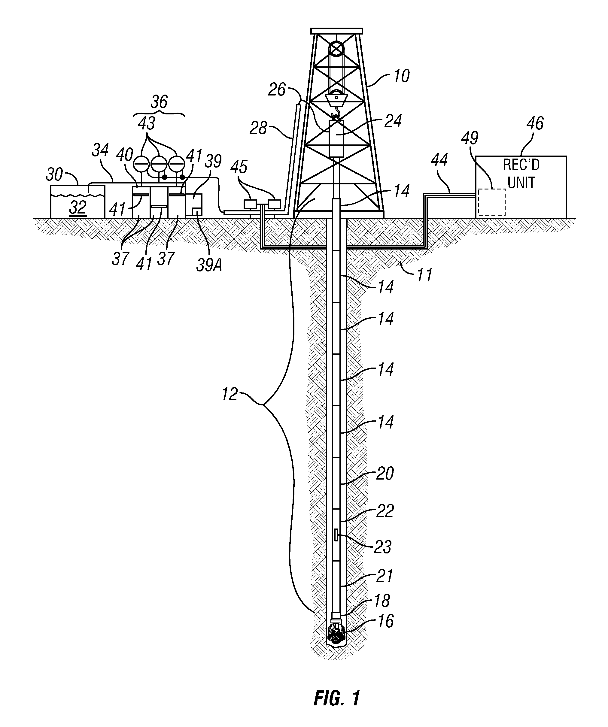
[0019]A typical wellbore drilling system, including a measurement while drilling (“MWD”) caliper device that can be used in according with various examples of the invention is shown schematically in FIG. 1. A hoisting unit called a “drilling rig” suspends a conduit of pipe called a drill string 12 in a wellbore 18 being drilled through subsurface rock formations, shown generally at 11. The drill string 12 is shown as being assembled by threaded coupling end to end of segments or “joints”14 of drill pipe, but it is within the scope of the present invention to use continuous pipe such as “coiled tubing” to operate a drilling system in accordance with the present invention. The rig 10 may include a device called a “top drive”24 that can rotate the drill string 12, while the elevation of the top drive 24 may be controlled by various winches, lines and sheaves (not identified separately) on the rig 10. A drill bit 16 is typically disposed at the bottom end of the drill string 12 to drill...


PUM


Abstract

A drill string caliper includes a mandrel configured to be coupled within a drill string. At least one laterally extensible arm is coupled to an exterior of the mandrel. A biasing device is configured to urge the at least one arm into contact with a wall of a wellbore. A sensor is configured to generate an output signal corresponding to a lateral extent of the at least one arm.

Description

RELATED APPLICATIONS[0001]The present application is a continuation-in-part application and claims priority from U.S. Pat. No. 8,024,868, entitled “Wall Contact Caliper Instruments for Use In a Drill String,” issued on Sep. 27, 2011, and claims priority from U.S. Patent Application Ser. No. 61 / 311,022 entitled “Wall Contact Caliper Instruments For Use in a Drill String,” which are both hereby incorporated by reference in their entireties.BACKGROUND OF THE DISCLOSURE[0002]Measurement while drilling (“MWD”) systems and methods generally include sensors disposed in or on components that are configured to be coupled into a “drill string.” A drill string is a pipe or conduit that is used to rotate a drill bit for drilling through subsurface rock formations to create a wellbore therethrough. A typical drill string is assembled by threadedly coupling end to end a plurality of individual segments (“joints”) of drill pipe. The drill string is suspended at the Earth's surface by a hoisting un...

Claims


Application Information

Patent Timeline
Patent Type & Authority Patents(United States)
IPC IPC(8): E21B47/08G01B5/12
CPCE21B47/08
Inventor BRANNIGAN, JAMES C.NOLD, III, RAYMOND V.RASMUS, JOHN C.GARCIA-OSUNA, FERNANDOZAZOVSKY, ALEXANDER
Owner SCHLUMBERGER TECH CORP
Why Eureka
Try Eureka