Imaging device information management system

a technology of information management system and imaging device, applied in the direction of digital output to print unit, instruments, digital computers, etc., can solve the problems of inability to know to which computer each imaging device is locally connected, inability to output indicative information in the conventional imaging device information management system, and inability to know the user of the system

Active Publication Date: 2013-07-23
BROTHER KOGYO KK
View PDF53 Cites 3 Cited by
  • Summary
  • Abstract
  • Description
  • Claims
  • Application Information

AI Technical Summary

Benefits of technology

[0010]The present invention is advantageous in that the above-described deficiencies of the conventional system can be resolved, and the information representing the relationship between the imaging device and the computers to which the imaging devices are locally connected can be provided. The present invention is also advantageous in that, even if all the imaging devices and the computers to which the imaging devices are connected are not simultaneously operating, the managing computer can obtain the information regarding the imaging devices.
[0023]Optionally, the second computer program product may further include instructions that cause the managing computer to realize a function of a display information creating system that creates display information including a correspondence between the managed computer and the imaging device in accordance with the correspondence information stored in the storage by the information storing system.
[0047]Furthermore, the imaging device information primary obtaining system may partially obtain the imaging device information from the imaging device at a time, and the imaging device information storing system may store the imaging device information in the storage after the imaging device information primary obtaining system has completed obtaining the imaging device information from the imaging device.
[0090]Further, the imaging device information primary obtaining system may partially obtain the imaging device information from the imaging device at a time, and the imaging device information storing system may store the imaging device information in the storage after the imaging device information primary obtaining system has completed obtaining the imaging device information from the imaging device.

Problems solved by technology

Therefore, from the managed information, it is impossible to know to which computer each imaging device is locally connected.
Therefore, the conventional imaging device information management system is unable to output information indicative of the relationship between each computer and the imaging devices locally connected thereto as a displayed image, a printed image of a file.
Therefore, the user of the system cannot know, using such a system, the relationship between the computers and locally connected imaging devices.
Further, in such a system, it is impossible for a computer to request another computer for such information or to transmit such information to another computer.
According to such a system, if the response is not provided by the imaging device immediately, the computer is unable to transmit the information immediately.
However, according to the publication, the imaging device only transmits the information regarding the imaging device itself, and no information regarding the computer to which the imaging device is connected.
Therefore, when receives the e-mail message from the imaging device, the user cannot identify the computer connected with the imaging device.

Method used


Image

  • Imaging device information management system
  • Imaging device information management system
  • Imaging device information management system

Examples


first embodiment

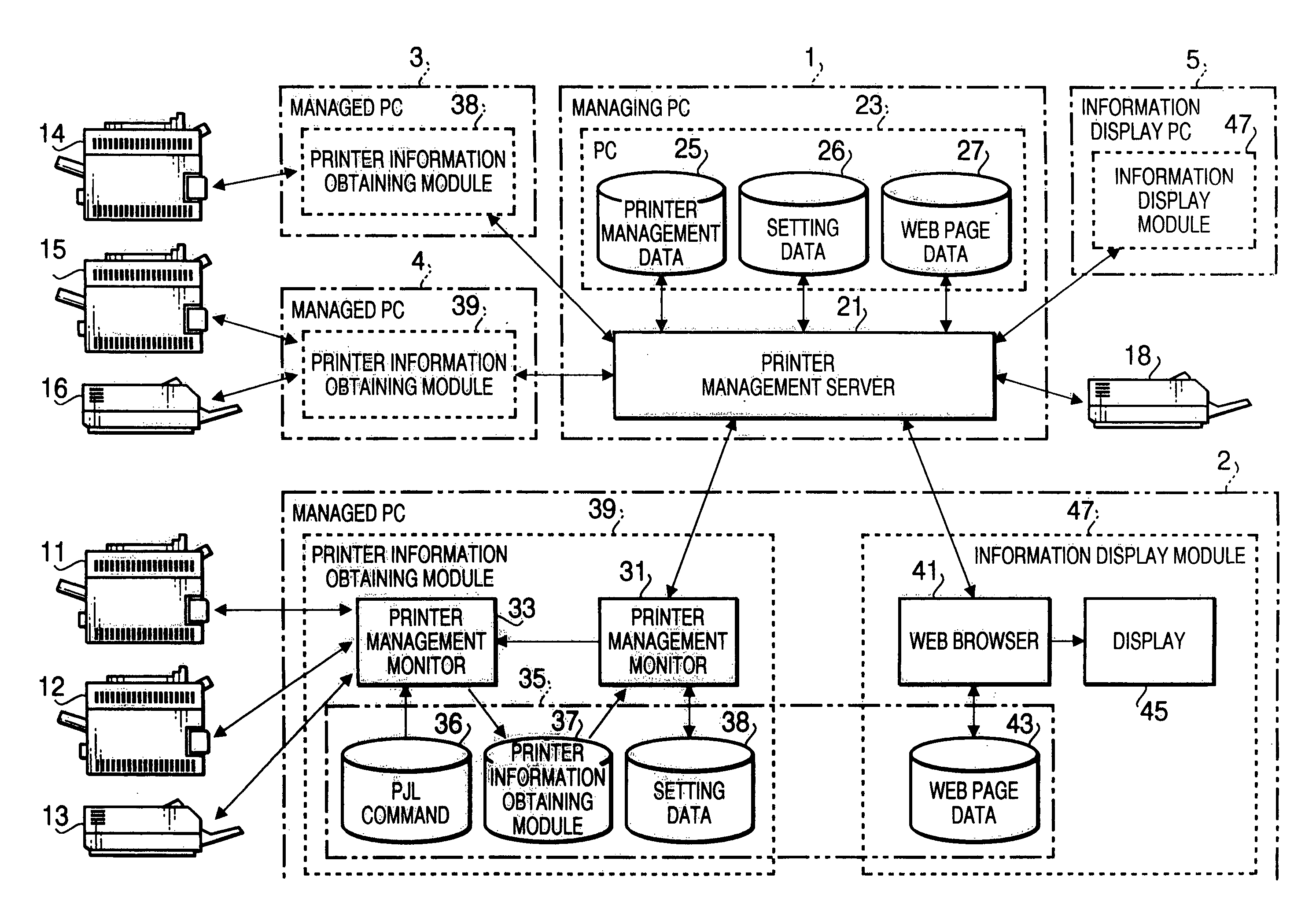
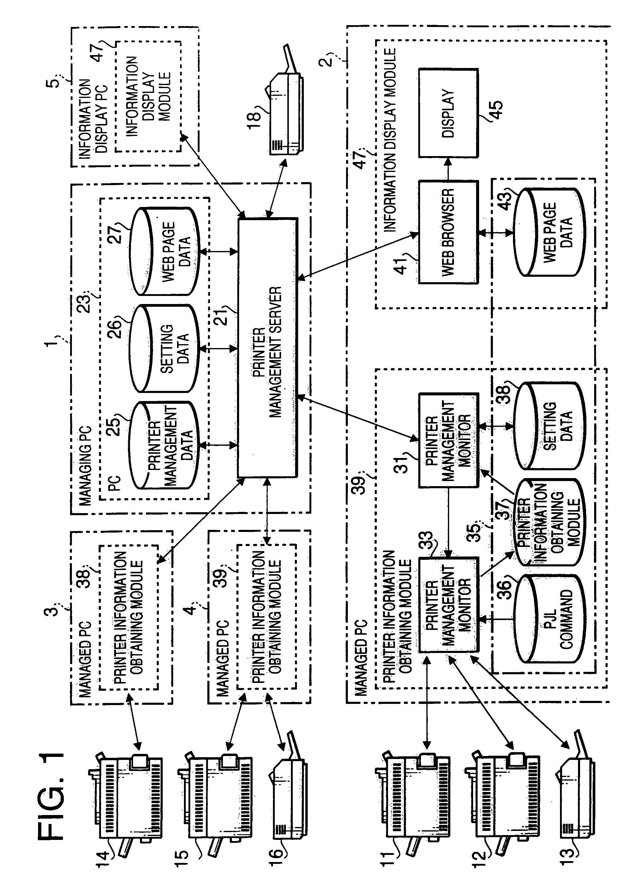
[0163]FIG. 1 schematically shows a configuration of an imaging device information management system (hereinafter, simply referred to as the information management system) 1000 according to the invention.

[0164]The information management system 1000 includes a plurality of personal computers (hereinafter referred to as PCs) 1-5 and a plurality of printers 11-16 locally connected to one PCs 2-4. The PCs 1-5 are interconnected through a LAN (Local Area Network).

[0165]Each of the PCs 1-5 is, as is well known, provided with a control unit having a CPU (Central Processing Unit), a ROM (Read Only Memory) and a RAM (Random Access Memory), an input unit having a keyboard and pointing device, an output unit having a display, and an auxiliary storage unit having a non-volatile data storage such as a hard disk.

[0166]The PCs 1-5 are implemented with Windows®, Linux® or MacOS® as an OS (Operating System). A basic functions such as an input function using the keyboard, an output function using the ...

second embodiment

[0345]Hereinafter, an information transmission system will be described with reference to FIGS. 25-37.

[0346]FIG. 25 is a block diagram showing a configuration of an information transmission system 2000 according to a second embodiment. In FIG. 25, external devices / system, which are outside of the information transmission system 2000, are also indicated for convenience of explanation.

[0347]As shown in FIG. 25, the information transmission system 2000 includes a PC (personal computer) 201 and a plurality of printers 202-204 connected to the PC 1.

[0348]The PC 201 has a control unit including CPU, ROM and RAM, an input unit including keyboard and pointing device, an output unit including a display, and an auxiliary storage unit including a non-volatile storage such as a hard disk. The PC 201 is implemented with an OS (e.g., Windows®, Linux® or MacOS®). Basic functions commonly used by applications are provided by the OS. The basic functions include input / output function such as input t...


PUM


Abstract

An imaging device information management system includes a plurality of computers interconnected through a network. A managed computer includes a primary imaging device information obtaining system that obtains imaging device information from the imaging device. A managing computer includes a computer information obtaining system that obtains computer information from the managed computer, a secondary imaging device information obtaining system that obtains the imaging device information obtained by the primary imaging device information obtaining system from the managed computer, and an information storing system that creates correspondence information representing a correspondence between the managed computer and the imaging device in accordance with the computer information obtained by the computer information obtaining system and the imaging device information obtained by the secondary imaging device information obtaining system, and stores the correspondence information in a storage.

Description

BACKGROUND OF THE INVENTION[0001]The present invention relates to an imaging device information management system that manages information of imaging devices which are locally connected to terminals connected to a network.[0002]Conventionally, there has been known a program called as a status monitor, which is executed on a computer to investigate and / or manage the status (e.g., on-line / off-line, busy, error, etc.) of devices (e.g., a printer or an MFP (multi-function peripheral) having a printer function) locally connected to the computer. There has also been known a program called as a maintenance tool, which is executed on a computer to manage maintenance information (e.g., remaining amount of toner or ink, remaining amount of a recording sheet, a term for exchanging a photosensitive drum, etc.) of imaging devices locally connected to the computer.[0003]The conventional status monitor and maintenance tool have been executed locally. Recently, however, a plurality of computers are...

Claims


Application Information

Patent Timeline
Patent Type & Authority Patents(United States)
IPC IPC(8): G06F15/173G06F3/12
CPCG06F3/1203G06F3/1229G06F3/1288G06F3/1226
Inventor KAWAI, SUNAO
Owner BROTHER KOGYO KK
Why Eureka
Try Eureka