Printing system

Inactive Publication Date: 2007-10-18
BROTHER KOGYO KK
View PDF40 Cites 11 Cited by
  • Summary
  • Abstract
  • Description
  • Claims
  • Application Information

AI Technical Summary

Benefits of technology

[0022] The present invention is advantageous in that the above-described deficiencies of conventional network systems can be resolved. That is, according to the present invention, improved network printing system is provided in which a confidential document is printed only when a recipient is close to a printer which outputs the confidential document without requiring a troublesome procedure such as inputting of passwords by the recipient. Alternatively or optionally, according to the invention, when a plurality of image forming devices are connected with a network system, an appropriate one is selected without requiring troublesome input operations by the user. Alternatively, in a printing system including a plurality of image forming devices, a print job is performed by a printer which is located close to a recipient of the output of the print job without requiring troublesome input operations by the recipient.
[0024] According to the above configuration, the following advantages are achieved.
[0029] With this configuration, since it is confirmed whether the image formation is to be started or not, unintentional starting of the image formation can be prevented.

Problems solved by technology

Therefore, a confidential documents will not be printed out and therefore viewed by an unintended recipient.
However, according to the above system, it is necessary to certify the recipient, and for this purpose, it typically requires a password to be input through the cell phone, which is troublesome.
Further, it is unnecessary for the recipient to manually input the password in response to the request from the printer.
It may be inconvenient since a dedicated ID card should be designed for the printing system.
Further, every user of the printing system must bring the ID card only for the purpose of initiating a print job.
However, according to the above-described system, if the user desires to switch a plurality of image forming devices, setting operations should be performed when the printers are switched, which is troublesome.
According to such a system, however, it is necessary for the recipient to input the information key through the printer, which is relatively troublesome.
Therefore, if the demander and the recipient are different, the information key should be notified from the demander to the recipient, which may not get along in a practical use.

Method used


Image

  • Printing system
  • Printing system
  • Printing system

Examples


first embodiment

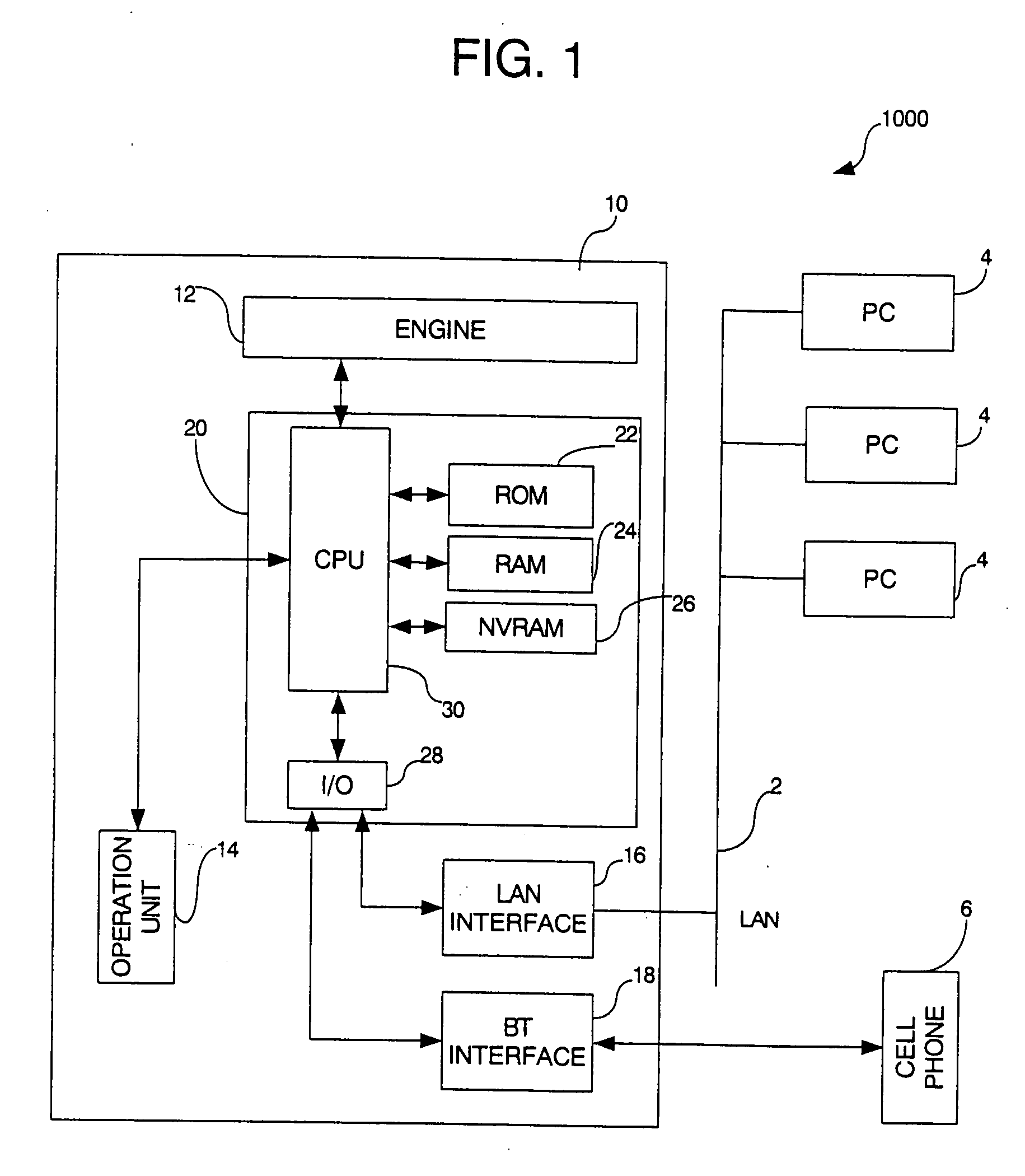
[0097]FIG. 1 is a block diagram showing a configuration of a printing system 1000 according to a first embodiment of the invention.

[0098] The printing system 1000 includes a printer 10, a plurality of personal computers (PCs) 4, and a cell phone 6. The printer 10 and the plurality of PCs 4 are interconnected through a LAN (Local Area Network) 2.

[0099] The printer 10 includes:

[0100] an engine 12 that operates to form an image on a recording sheet;

[0101] an operation unit 14 having manually operable keys, through which a user can input various commands, and a display device for displaying various information;

[0102] a LAN interface 16 that performs data exchange through the LAN;

[0103] a BT (Bluetooth interface) 18 that transmits / receives data in accordance with a Bluetooth communication method; and

[0104] a main controller 20 that controls the above-described components of the printer 10.

[0105] The main controller 20 includes a ROM 22 that stores various programs for operations ...

second embodiment

[0150] A structure of the printer according to the second embodiment is substantially the same as that of the first embodiment except that a size of the communication area of the BT interface 18 and the PRINT PROCEDURE executed by the CPU 30 are different. Therefore, in the following description of the second embodiment, components similar to those in the first embodiment are given the same reference numerals and description thereof will be simplified.

[0151] In the second embodiment, the transmission power of the BT interface 18 and the cell phone 6 fall within class 1. Accordingly, the BT interface 18 is capable of communicating with the cell phone 6 (BT communication device) within a circle whose radius is approximately 100 m (i.e., the radius of the Piconet area is approximately 100 m).

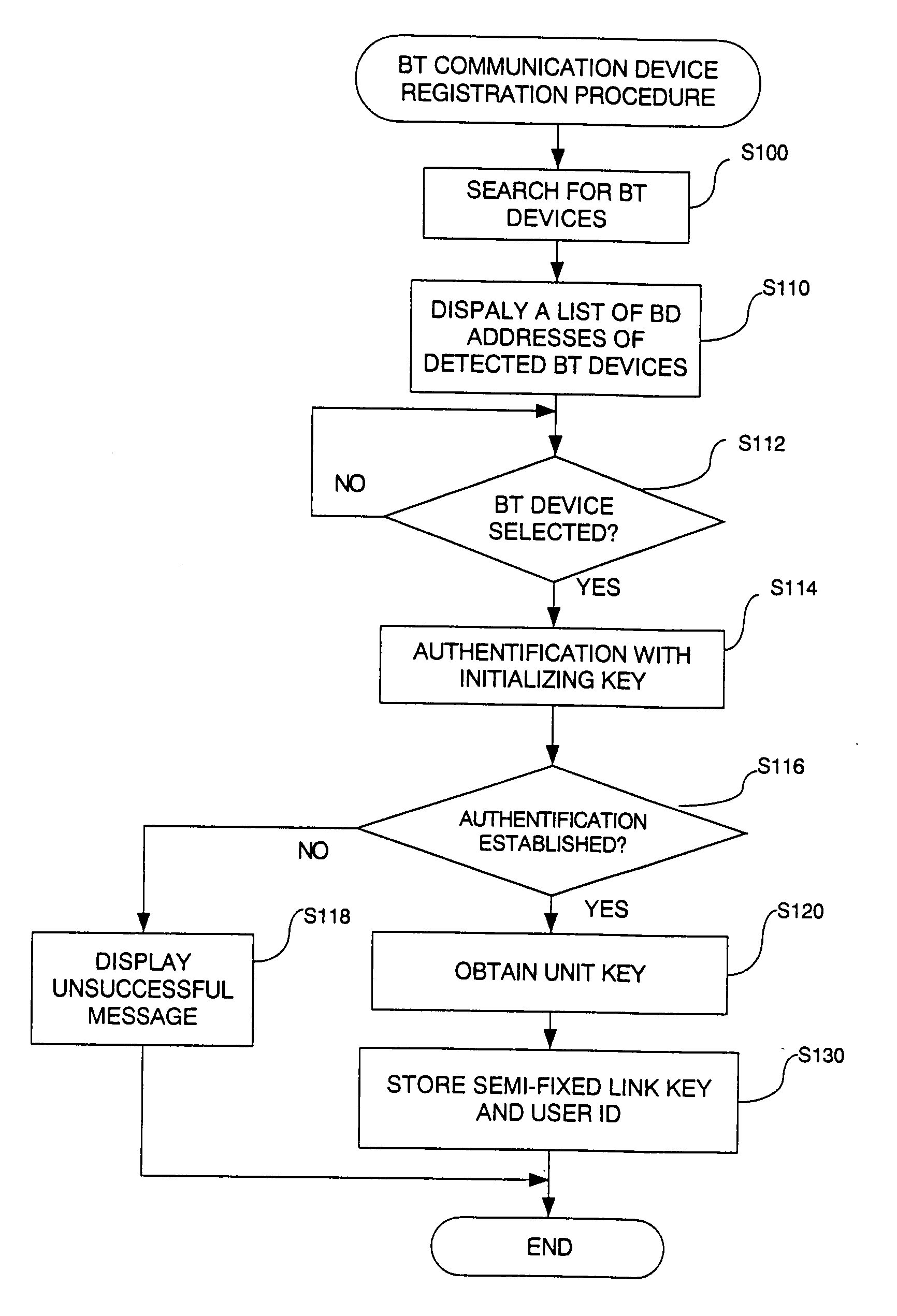
[0152]FIG. 5 is a flowchart illustrating a PRINT PROCEDURE according to a second embodiment.

[0153] The PRINT PROCEDURE shown in FIG. 5 is different from that shown in FIG. 3 in that steps S300 a...

third embodiment

[0179]FIG. 7 is a block diagram of a data management system 2000 according to a third embodiment of the invention.

[0180] As shown in FIG. 7, the data management system 2000 includes a file server 100 that stores and manages image data files representative of letters, characters, symbols and figures to be printed, a plurality of printers 10M, a plurality of workstations 40, which are interconnected through a network (LAN) 2 so that bi-directional data communication can be performed therebetween.

[0181] The server 100 of the data management system 2000 includes a CPU 101 that controls entire operation of the server 100, a ROM 102 that stores programs to be executed by the CPU 101, a RAM 103 that temporarily stores data when the programs are executed by the CPU 101, and a communication unit 104 that performs the bi-directional data communication with the printers 10M and / or workstations 40 through the network 2. The server 100 further includes a hard disk drive (HDD) 105, and in the H...


PUM


Abstract

An imaging system is provided with an authentication data storage that stores a plurality of pieces of authentication data in relationship to user If)s respectively representing owners of the plurality of communication devices. Further included is a reading system that reads out one of the plurality of pieces of the authentication data corresponding to a user ID if the user ID is transmitted from the external device in relationship to the image data, and a searching system searches for a communication device with which a connection authentication is established using the authentication data read out by the reading system within a predetermined communication area with respect to the imaging system. An imaging system forms an image represented by the image data transmitted in relationship to the user ID from the external device when the communication device is detected by the searching system.

Description

[0001] This is a Division of application Ser. No. 10 / 290,178 filed on Nov. 8, 2002. The disclosure of the prior application is herby incorporated by reference herein in its entirety.BACKGROUND OF THE INVENTION [0002] The present invention relates to a printing system including a printer and a plurality of terminal devices, which are interconnected through a network system. [0003] Conventionally, a printing system including an image forming device such as a printer, and at least one external device interconnected through a network system has been known. Typically, the image forming device is located remote from the external device. In such a system, it may happen that a confidential document is to be printed, i.e., printing data of the confidential document may be transmitted to the image forming device through the network so that the confidential document is printed by the image forming device. In such a case, if the image forming device prints out the confidential document as soon ...

Claims


Application Information

Patent Timeline
IPC IPC(8): G06F15/173G06F3/12G06F21/60
CPCG06F21/608H04N1/00222H04N1/00233H04N1/00307H04N1/4413H04N2201/0082H04N2201/0039H04N2201/0043H04N2201/0049H04N2201/0055H04N1/444
Inventor HIBINO, MASAAKIMAEKAWA, YOHEIFUKAZAWA, KOSHI
Owner BROTHER KOGYO KK
Why Eureka
Try Eureka