System for a hydraulic rotator

a technology of hydraulic rotators and rotors, applied in the direction of toothed gearings, constructions, gearings, etc., can solve the problems of affecting the operation of front-loaders, skid steers, excavators, and equipment that cannot bear the weight of itself, an attachment, the targeted item of the attachment, and the torque load and stress involved in any rotation, so as to achieve the effect of more rotation flexibility

Active Publication Date: 2021-09-14
LOUDEN DARRELL WAYNE
View PDF25 Cites 0 Cited by
  • Summary
  • Abstract
  • Description
  • Claims
  • Application Information

AI Technical Summary

Benefits of technology

[0005]The present invention is a system that operators of heavy equipment can rely on and resolves the deficiencies found in prior inventions. The system generally comprises universal quick attach plates, bearing mounting plates, a hydraulic motor attached to hydraulic hoses to power the system, a bearing that is strong enough to hold a substantial amount of weight, and a driving mechanism to drive the hydraulic rotator. The hydraulic rotator can be adapted for, but is not limited to, front-loaders, skid steers, and excavators. The hydraulic rotator will eliminate existing problems seen in present inventions such as a Marshall Tree Saw only cutting trees from a horizontal position and not possessing the capability to further pick up cut tree limbs and debris and move them without fear of the machine crippling under the immense weight. Further, the hydraulic rotator of the present invention eliminates operator concern for the degree of angle or stress grade for which the machine is set on. Operators of such heavy equipment can now rotate and move heavy items without the constant worry of their equipment being damaged from the constant operation of the equipment as well as the difficult maneuvering of the machine into position on a hillside or slope. The present invention saves operators time and money by providing a reliable hydraulic rotator capable of sustained operation under the weight, torque load and stress of the combined elements often encountered in the field, at any degree of angle. The invention also reduces maintenance and replacement costs. Although described herein principally in terms of a hydraulic system, the invention is not limited to only hydraulic systems and may be used in electro-mechanical and hybrid systems.
[0007]The present invention is attached to equipment, such as a front-loader, by an inner quick attach plate. A drive assembly comprising a drive motor and a bearing are disposed on the exterior of the inner quick attach plate that is secured to the equipment, and may also be secured to an intermediate bearing plate. The bearing, which may be a slew ring bearing, is secured to an outer quick attach plate, and may also be secured to a second intermediate bearing plate such that the drive assembly, including drive motor and bearing, are not directly attached to the inner and outer quick attach plates. The assembly is able to rotate the outer quick attach plate 360 degrees with respect to the inner quick attach plate and is able to withstand the substantial load that would typically be placed on the drive assembly by the weight of the outer quick attach plate and any attachment. The drive assembly may be powered by a hydraulic drive motor that uses either a cogwheel gear or worm gear drive to rotate the toothed outer portion of the bearing.
[0008]The present invention utilizes existing quick attach systems but enables the attachment itself to be rotated with respect to its mounting frame. For example, when attached using the hydraulic rotator system of the present invention, a Marshall Tree Saw attached to a front-loader would be able to rotate 360 degrees with respect to the front-loader. The rotation point may be adjusted such that the bearing in the drive system of the present invention is offset with respect to the center of the quick attach plate, providing or ease of use in small spaces or near structures.
[0017]The bearing is again a slewing or slew ring bearing capable of holding immense amounts of weight. The bearing is connected on a first end to the outside of the second end of the housing via the inner set of bearing bolts and is connected on a second end to the first end of the second bearing mounting plate via the outer set of bearing bolts which ultimately bolt to the second end of the second bearing mounting plate. The inner and outer bearing bolts offset one another and the amount of each is determined on the specifications requested by the operator. Advantageously, depending on the operator's preference, the slewing or slew ring bearing can be located in the center of the housing, or offset to the left or the right. When offset to the left or the right, it will allow the operator more rotation flexibility for working closely along fences and buildings.

Problems solved by technology

Currently, operators of front-loaders, skid steers, and excavators cannot rely on their equipment to bear the weight of itself, an attachment, and the targeted item of the attachment, as well as the torque load and stress involved with any rotation.
The Marshall Tree Saw or similar attachment can only be operated in the horizontal position thus making it harder to cut trees or brush from any position or to pick up and carry downed trees or brush.

Method used


Image

  • System for a hydraulic rotator
  • System for a hydraulic rotator
  • System for a hydraulic rotator

Examples


Embodiment Construction

[0026]The present invention will now be described in more detail with reference to exemplary embodiments as shown in the accompanying drawings. While the present invention is described herein with reference to the exemplary embodiments, it should be understood that the present invention is not limited to such exemplary embodiments. Those possessing ordinary skill in the art and having access to the teachings herein will recognize additional implementations, modifications, and embodiments, as well as other applications for use of the invention, which are fully contemplated herein as within the scope of the present invention as disclosed and claimed herein, and with respect to which the present invention could be of significant utility.

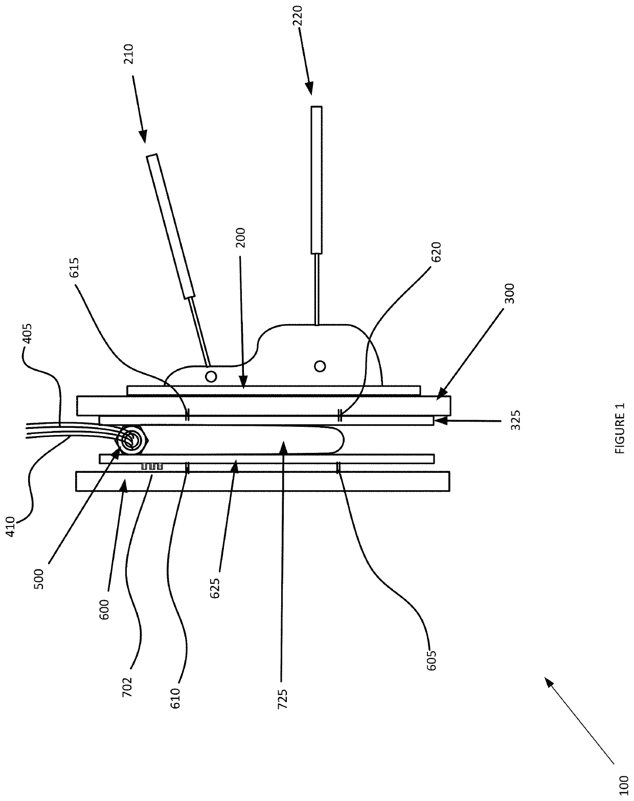
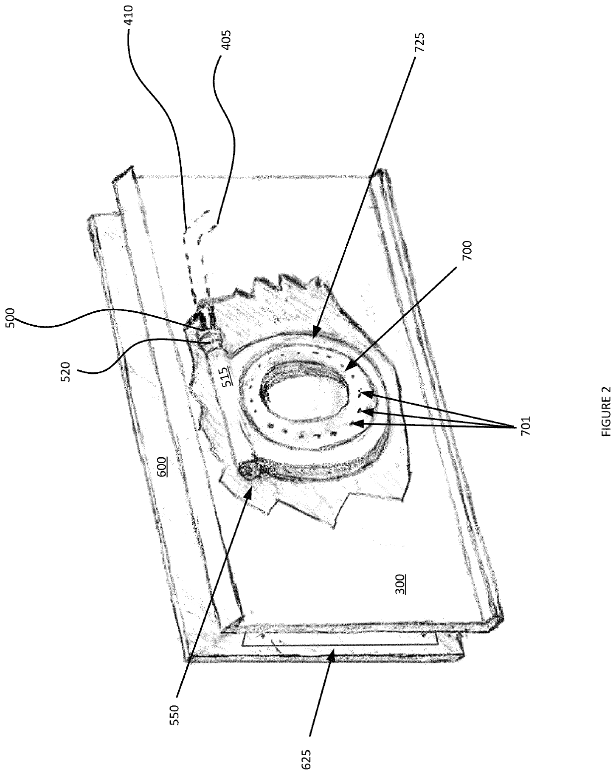
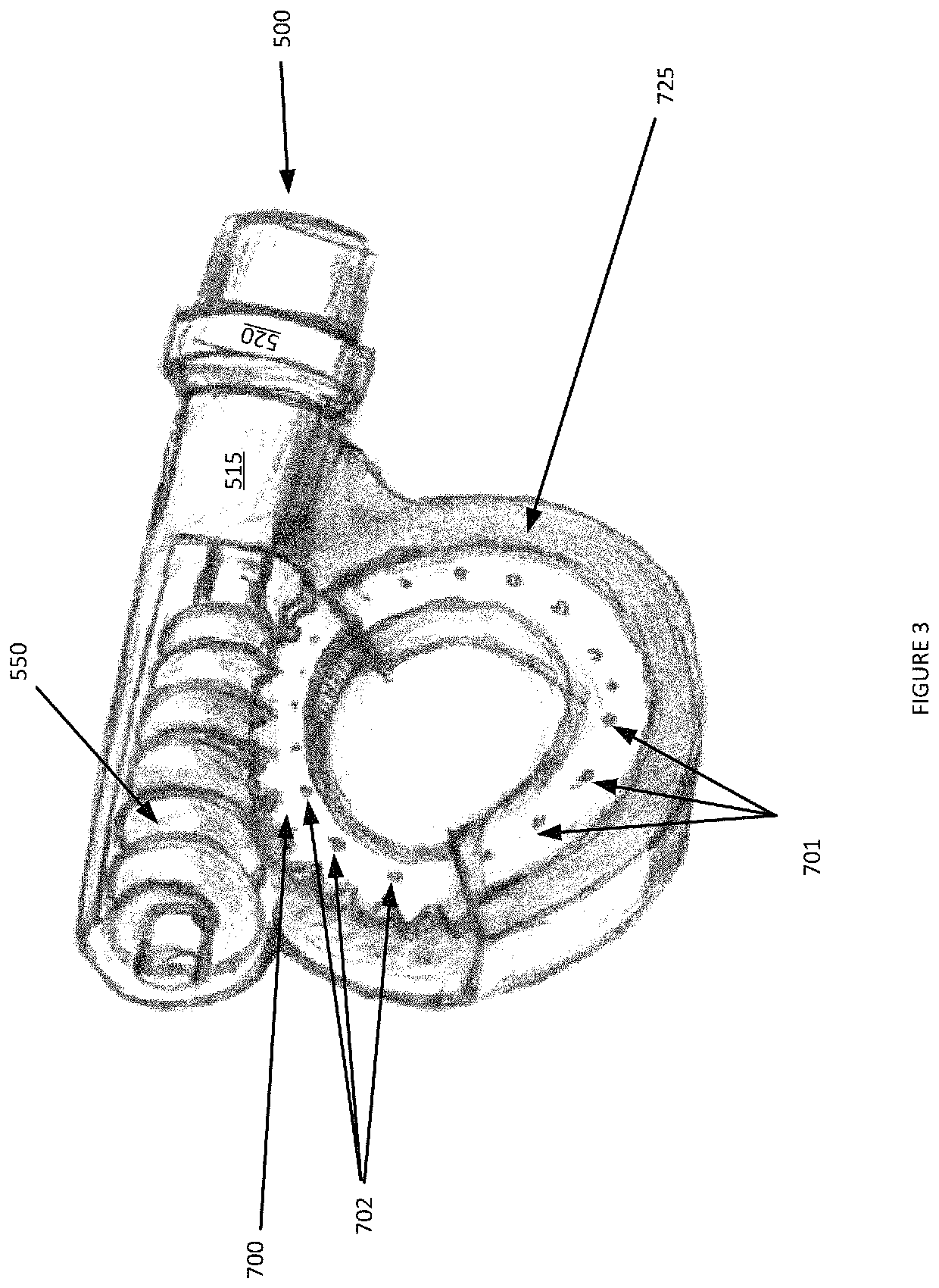
[0027]There are two similar but unique embodiments of the hydraulic rotator apparatus. In a first exemplary embodiment, the hydraulic rotator is more compact and lighter because there is only one driving mechanism present, which is a worm drive. One exe...


PUM


Abstract

The invention relates generally to hydraulic rotator. More specifically, the invention relates to a system that provides for the successful three hundred and sixty-degree, clockwise or counterclockwise rotation of heavy weights. The system successfully bears the weight of the equipment, the hydraulic rotator, the attachment to the hydraulic rotator and the materials being targeted by the attachment, as well as the torque load and stress produced by the successful three-hundred-and-sixty-degree rotation.

Description

CROSS-REFERENCE TO RELATED APPLICATION[0001]The present invention claims benefit of priority to U.S. Provisional Application No. 62 / 451,247, entitled SYSTEM FOR A HYDRAULIC ROTATOR, Louden, filed Jan. 27, 2017, which is incorporated by reference herein in its entirety.FIELD OF THE INVENTION[0002]The present invention generally relates to a system for a hydraulic or electro-mechanical rotator. More specifically, a hydraulic or electro-mechanical rotator system is provided that is capable of sustained operation under the weight, torque load and stress of the combined elements often encountered in the field.BACKGROUND OF THE INVENTION[0003]Operators of equipment, such as skid steers, front-loaders, or excavators need to be able to have full confidence in the equipment they are operating. Individuals of ordinary skill in the art understand that reliability of skid steers, excavators and front-loaders revolves around the equipment's ability to support the immense amount of weight of not ...

Claims


Application Information

Patent Timeline
Patent Type & Authority Patents(United States)
IPC IPC(8): F16H1/16E02F3/36
CPCF16H1/16E02F3/3681
Inventor LOUDEN, DARRELL WAYNE
Owner LOUDEN DARRELL WAYNE
Why Eureka
Try Eureka