Measuring method of refractive index and measuring apparatus of refractive index

a technology of refractive index and measuring apparatus, which is applied in the direction of phase-affecting property measurement, measurement devices, instruments, etc., can solve the problems of measurement errors, time-consuming and strict centering or slope adjustment, and difficult measurements, and achieve fast and highly precise measurements.

Inactive Publication Date: 2013-08-27
CANON KK
View PDF3 Cites 0 Cited by
  • Summary
  • Abstract
  • Description
  • Claims
  • Application Information

AI Technical Summary

Benefits of technology

[0007]The present invention provides a measuring method and a measuring apparatus, which can provide quick and highly precise measurements of a refractive index of a test object.

Problems solved by technology

The method disclosed in JP 11-344313 has difficulties in measurements when the test object, such as a lens having a curved surface, decenters or tilts relative to the optical axis, and needs time-consuming strict centering or slope adjustments.
Otherwise, measured value would contain errors due to the influence of the curvature of the reflected surface.
The method disclosed in JP 02-008726 needs time-consuming adjustments of the refractive index of the matching oil due to blending of different types of oils.

Method used


Image

  • Measuring method of refractive index and measuring apparatus of refractive index
  • Measuring method of refractive index and measuring apparatus of refractive index
  • Measuring method of refractive index and measuring apparatus of refractive index

Examples


first embodiment

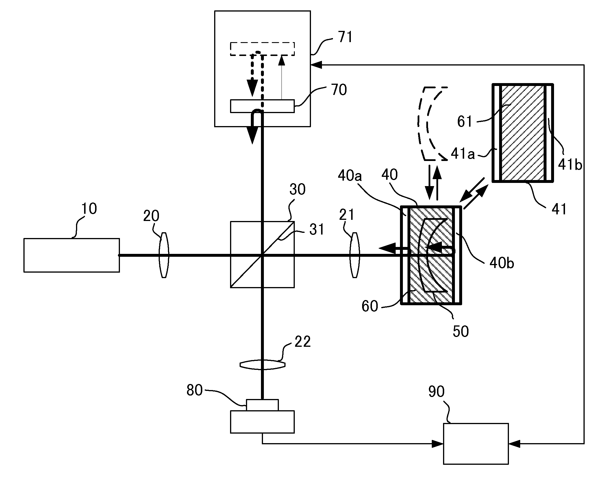
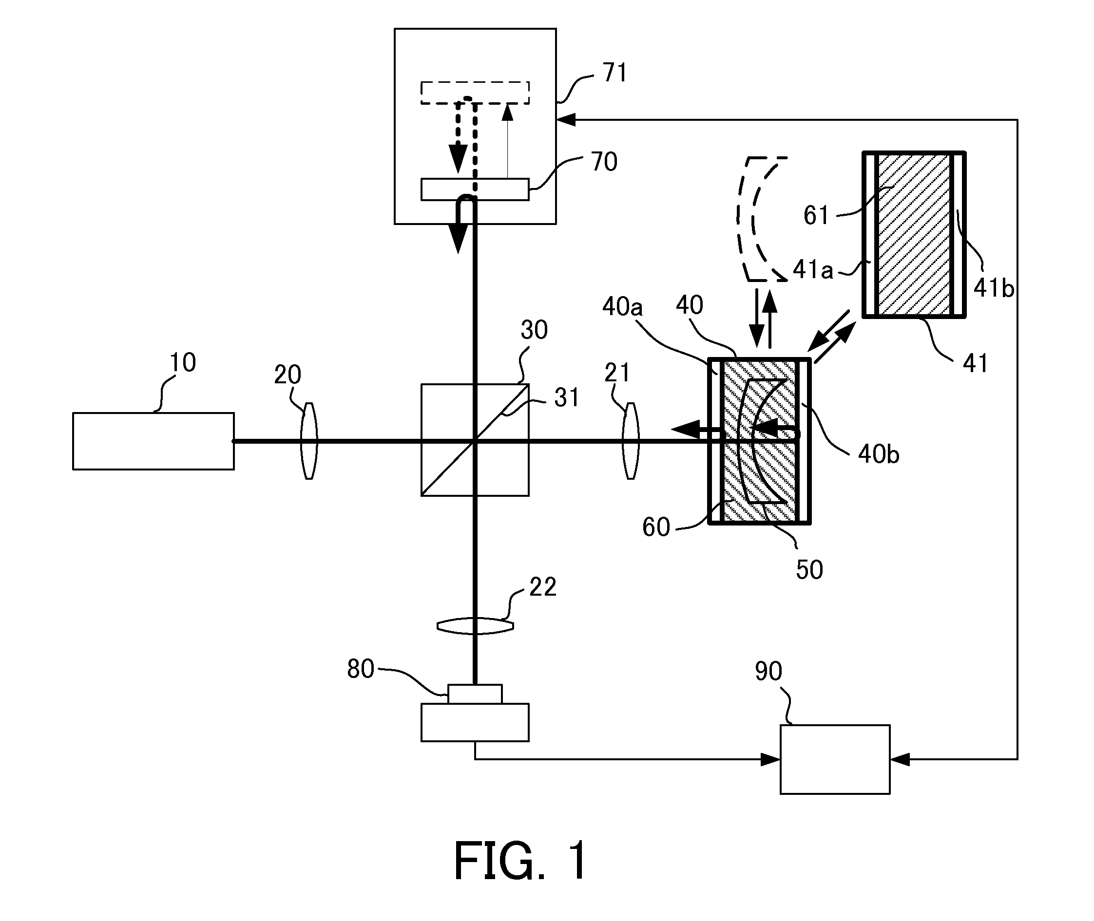
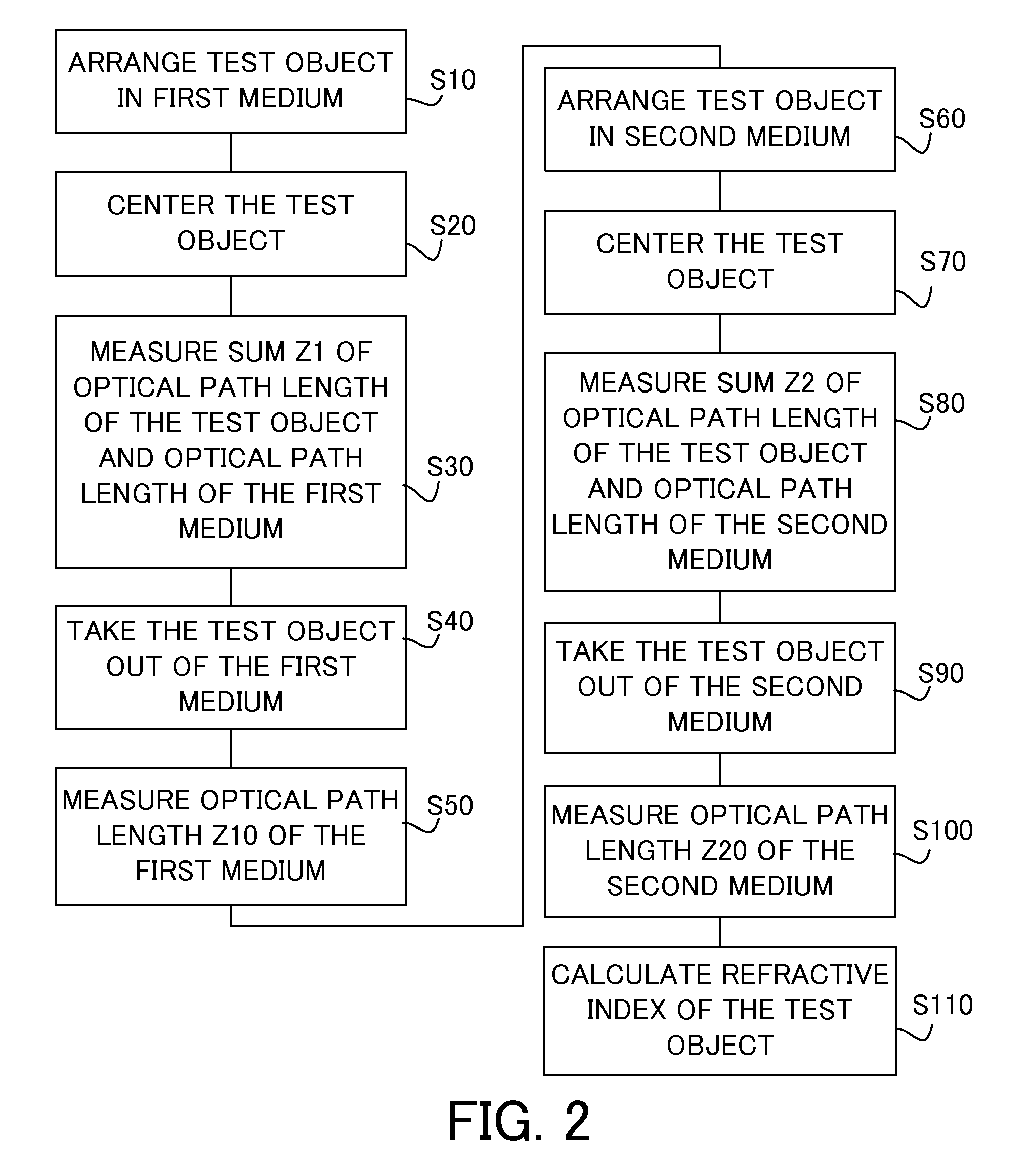
[0017]FIG. 1 is a block diagram of a measuring apparatus (low-coherence interferometer) according to a first embodiment. The measuring apparatus of this embodiment finds a refractive index of a test object by measuring a sum of an optical path length of the test object and an optical path length of each of two types of media in which the test object is arranged and an optical path length of each medium from which the test object is removed. The test object of this embodiment is a lens having a negative power, but the measuring apparatus can measure refractive indices of any test objects and the test object may be a lens or a flat plate as long as the test object is a refracting optical element.

[0018]The measuring apparatus includes a light source 10, an interference optical system, a mirror (reference unit) 70, a container, such as a first container 40 and a second container 41, configured to house a medium and a test object, a detector 80, and a computer 90, and is configured to me...

second embodiment

[0064]FIG. 3 is a block diagram of a measuring apparatus of this embodiment, and those elements in this embodiment which are the same as corresponding elements in the first embodiment will be designated by the same reference numerals. The test object 50 of this embodiment is a lens having a positive power but may be a flat plate, similar to the first embodiment.

[0065]The measuring apparatus of this embodiment includes a spectrometer 85 configured to analyze the interference signal in a spectral range, and to detect the spectral band intensity of the interference light instead of the detector 80, and the computer 90 obtains the detection result (measurement result) from the spectrometer 85. In addition, the measuring apparatus of this embodiment makes the side 40b of a transparent material, provides the mirror 45 behind it, and arranges a compensating plate 25 and a container 43 between the beam splitter 30 and the movable mirror.

[0066]The first container 40 is configured to house th...

third embodiment

[0090]FIG. 5 is a block diagram of the measuring apparatus of a third embodiment, and those elements in FIG. 5 which are corresponding elements in the first embodiment are designated by the same reference numerals. The measuring apparatus of this embodiment measures, during one scanning of the mirror 70, both a sum of the optical path length of the medium and the optical path length of the test object while the test object is arranged in each of two types of media having different refractive indices, and the optical path length of the medium in which the test object is not arranged in the optical path, and finds the refractive index of the test object using a measurement results.

[0091]The measuring apparatus of this embodiment measures, during one scanning of the mirror 70, both the sum of the optical path length of the test object and the optical path length of the medium in which the test object is arranged in the optical path, and the optical path length of the medium in which th...


PUM

PropertyMeasurementUnit
optical path lengthaaaaaaaaaa
refractive indexaaaaaaaaaa
refractive indicesaaaaaaaaaa

Abstract

A measuring method includes measuring a sum of an optical path length of a test object and a first medium in a first container, introducing light into an area that includes the first medium but does not include the test object and measuring the optical path length of the first medium, measuring a sum of the optical path length of the test object and a second medium in a second container, the second medium having a refractive index different from that of the first medium, introducing the light into an area that includes the second medium but does not include the test object and of measuring the optical path length of the second medium, and calculating a refractive index of the test object based on the measured optical path lengths and an actual distance of an optical path for which each optical path length is measured.

Description

BACKGROUND OF THE INVENTION[0001]1. Field of the Invention[0002]The present invention relates to a measuring method of a refractive index and a measuring apparatus of a refractive index.[0003]2. Description of the Related Art[0004]Japanese Patent Laid-Open No. (“JP”) 11-344313 proposes a method for fixing a test object between two transparent plates via intervals among them, for measuring an optical path length between the transparent plates, an optical path length between the transparent plate and the test object, and an optical path length in the test object, and for calculating a refractive index of the test object based on the measurement results. JP 02-008726 proposes a method for measuring a refractive index of a test object by immersing a glass sample having a known refractive index and a known shape and the test object in each of two types of matching oils having different refractive indices.[0005]The method disclosed in JP 11-344313 has difficulties in measurements when the...

Claims


Application Information

Patent Timeline
Patent Type & Authority Patents(United States)
IPC IPC(8): G01N21/41G01N21/43
CPCG01N21/41G01N21/45
Inventor SUGIMOTO, TOMOHIRO
Owner CANON KK
Why Eureka
Try Eureka