Measuring method of refractive index and measuring apparatus of refractive index
a technology of refractive index and measuring apparatus, which is applied in the direction of phase-affecting property measurement, measurement devices, instruments, etc., can solve the problems of measurement errors, time-consuming and strict centering or slope adjustment, and difficult measurements, and achieve fast and highly precise measurements.
- Summary
- Abstract
- Description
- Claims
- Application Information
AI Technical Summary
Benefits of technology
Problems solved by technology
Method used
Image
Examples
first embodiment
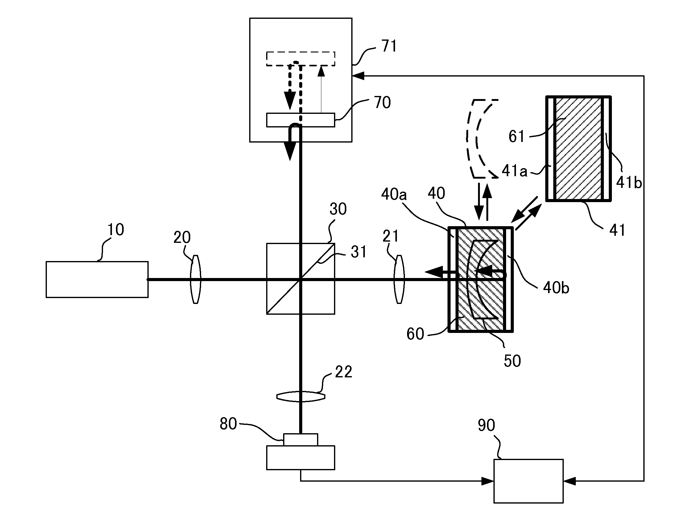
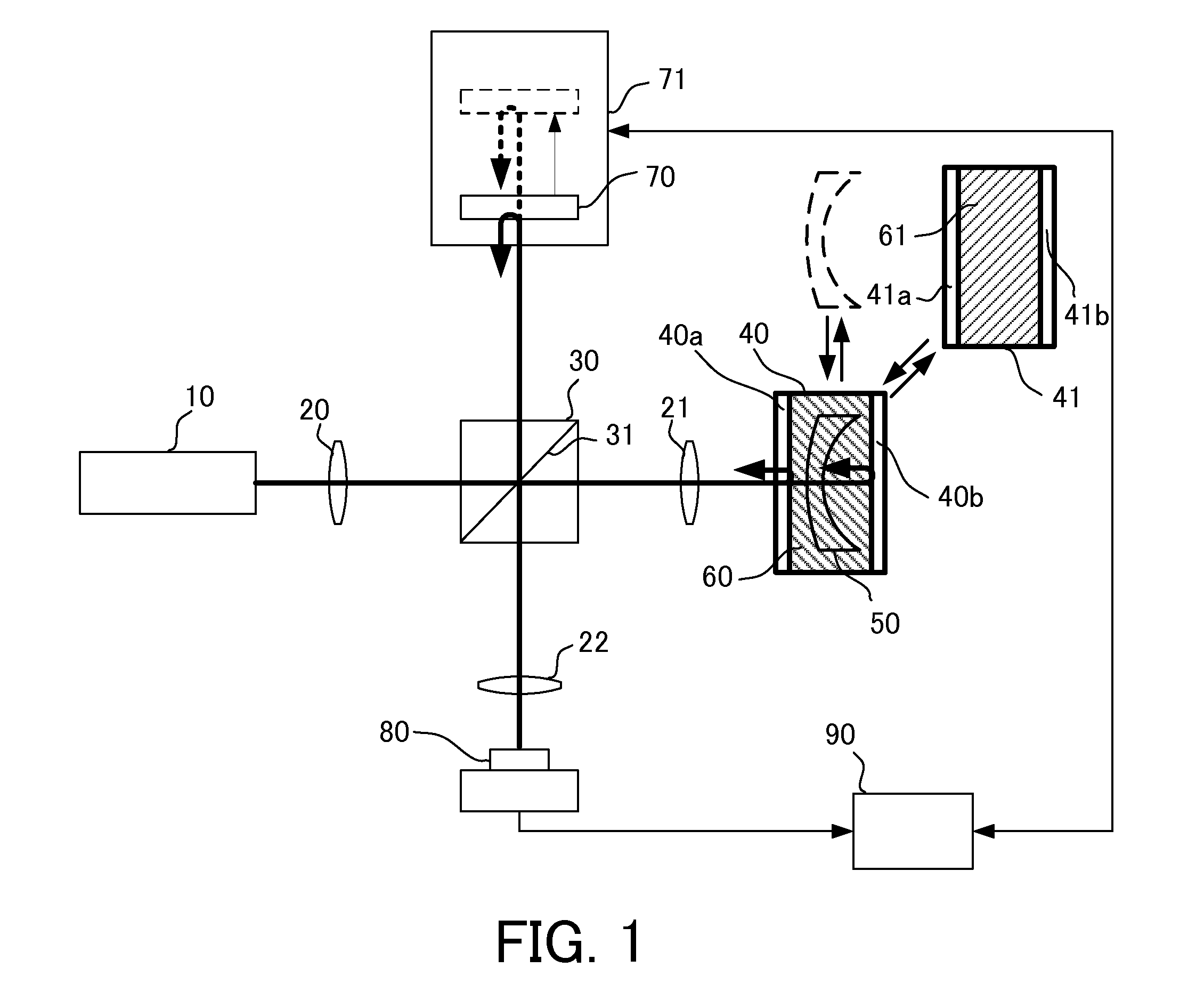
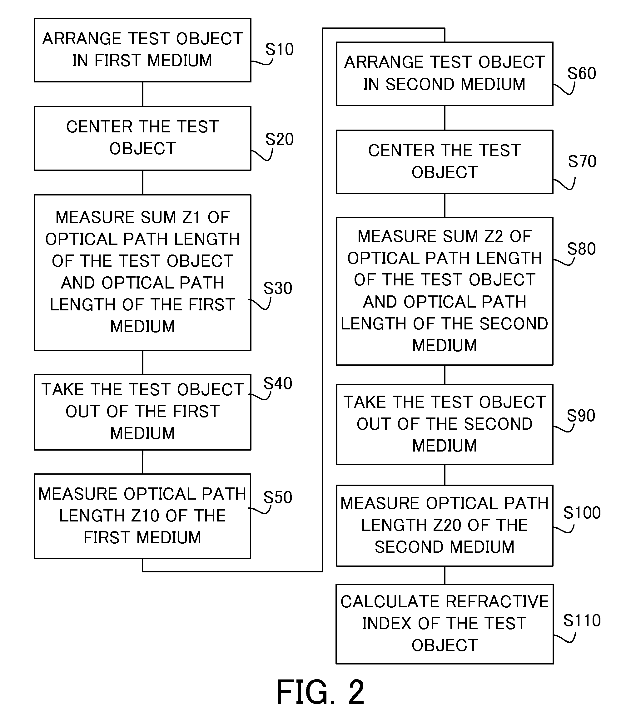
[0017]FIG. 1 is a block diagram of a measuring apparatus (low-coherence interferometer) according to a first embodiment. The measuring apparatus of this embodiment finds a refractive index of a test object by measuring a sum of an optical path length of the test object and an optical path length of each of two types of media in which the test object is arranged and an optical path length of each medium from which the test object is removed. The test object of this embodiment is a lens having a negative power, but the measuring apparatus can measure refractive indices of any test objects and the test object may be a lens or a flat plate as long as the test object is a refracting optical element.
[0018]The measuring apparatus includes a light source 10, an interference optical system, a mirror (reference unit) 70, a container, such as a first container 40 and a second container 41, configured to house a medium and a test object, a detector 80, and a computer 90, and is configured to me...
second embodiment
[0060]FIG. 3 is a block diagram of a measuring apparatus of this embodiment, and those elements in this embodiment which are the same as corresponding elements in the first embodiment will be designated by the same reference numerals. The test object 50 of this embodiment is a lens having a positive power but may be a flat plate, similar to the first embodiment.
[0061]The measuring apparatus of this embodiment includes a spectrometer 85 configured to analyze the interference signal in a spectral range, and to detect the spectral band intensity of the interference light instead of the detector 80, and the computer 90 obtains the detection result (measurement result) from the spectrometer 85. In addition, the measuring apparatus of this embodiment makes the side 40b of a transparent material, provides the mirror 45 behind it, and arranges a compensating plate 25 and a container 43 between the beam splitter 30 and the movable mirror.
[0062]The first container 40 is configured to house th...
third embodiment
[0082]FIG. 5 is a block diagram of the measuring apparatus of a third embodiment, and those elements in FIG. 5 which are corresponding elements in the first embodiment are designated by the same reference numerals. The measuring apparatus of this embodiment measures, during once scanning of the mirror 70, both a sum of the optical path length of the medium and the optical path length of the test object while the test object is arranged in each of two types of media having different refractive indices, and the optical path length of the medium in which the test object is not arranged in the optical path, and finds the refractive index of the test object using a measurement results.
[0083]The measuring apparatus of this embodiment measures, during once scanning of the mirror 70, both the sum of the optical path length of the test object and the optical path length of the medium in which the test object is arranged in the optical path, and the optical path length of the medium in which ...
PUM
| Property | Measurement | Unit |
|---|---|---|
| optical path length | aaaaa | aaaaa |
| optical path length | aaaaa | aaaaa |
| refractive index | aaaaa | aaaaa |
Abstract
Description
Claims
Application Information
 - R&D
- Intellectual Property
- Life Sciences
- Materials
- Tech Scout
- Unparalleled Data Quality
- Higher Quality Content
- 60% Fewer Hallucinations
Browse by: Latest US Patents, China's latest patents, Technical Efficacy Thesaurus, Application Domain, Technology Topic, Popular Technical Reports.
© 2025 PatSnap. All rights reserved.Legal|Privacy policy|Modern Slavery Act Transparency Statement|Sitemap|About US| Contact US: help@patsnap.com


