Valve lash adjustment system for a split-cycle engine

a technology of valve lash and split-cycle engine, which is applied in the direction of valve drives, machines/engines, mechanical equipment, etc., can solve the problems of thermal expansion effect variations of set valve lash due to thermal expansion effects, general flexibility is limited, and the ramp height is not required

Inactive Publication Date: 2013-09-17
SKADERI GRUP LLC
View PDF38 Cites 3 Cited by
  • Summary
  • Abstract
  • Description
  • Claims
  • Application Information

AI Technical Summary

Problems solved by technology

A cam driven actuation mechanism is efficient, fast and may be part of a variable valve actuation system, but generally has limited flexibility.
It should be noted that support elements may be subject to some high frequency vibration primarily caused by the high frequency movements of the actuating elements of a valve train, which apply forces to the support elements during operation.
Problematically, variations in a set valve lash due to thermal expansion effects may actually be greater than the ramp height required for such valves.
This means that if the valve lash is set large enough to account for thermal expansion, the tips of these inwardly opening crossover valves could miss the landing ramp altogether, which would cause the valves to repeatedly crash against their valve seats and prematurely damage the valves.
For any particular valve train actuating element, if the minimum mass required for adequate stiffness exceeds the maximum mass allowable for maximum operating speed, the element cannot be used in the valve train.
Moreover, this bending problem would increase proportionally as the length of the lever arm 78 increases.
Generally too, prior art HLAs (such as HLA 82), because of the compressibility of oil contained therein, are normally one of the main contributing factors in reducing valve train stiffness which, in turn, limits the maximum engine operating speed at which the valve train can safely operate.

Method used


Image

  • Valve lash adjustment system for a split-cycle engine
  • Valve lash adjustment system for a split-cycle engine
  • Valve lash adjustment system for a split-cycle engine

Examples


Embodiment Construction

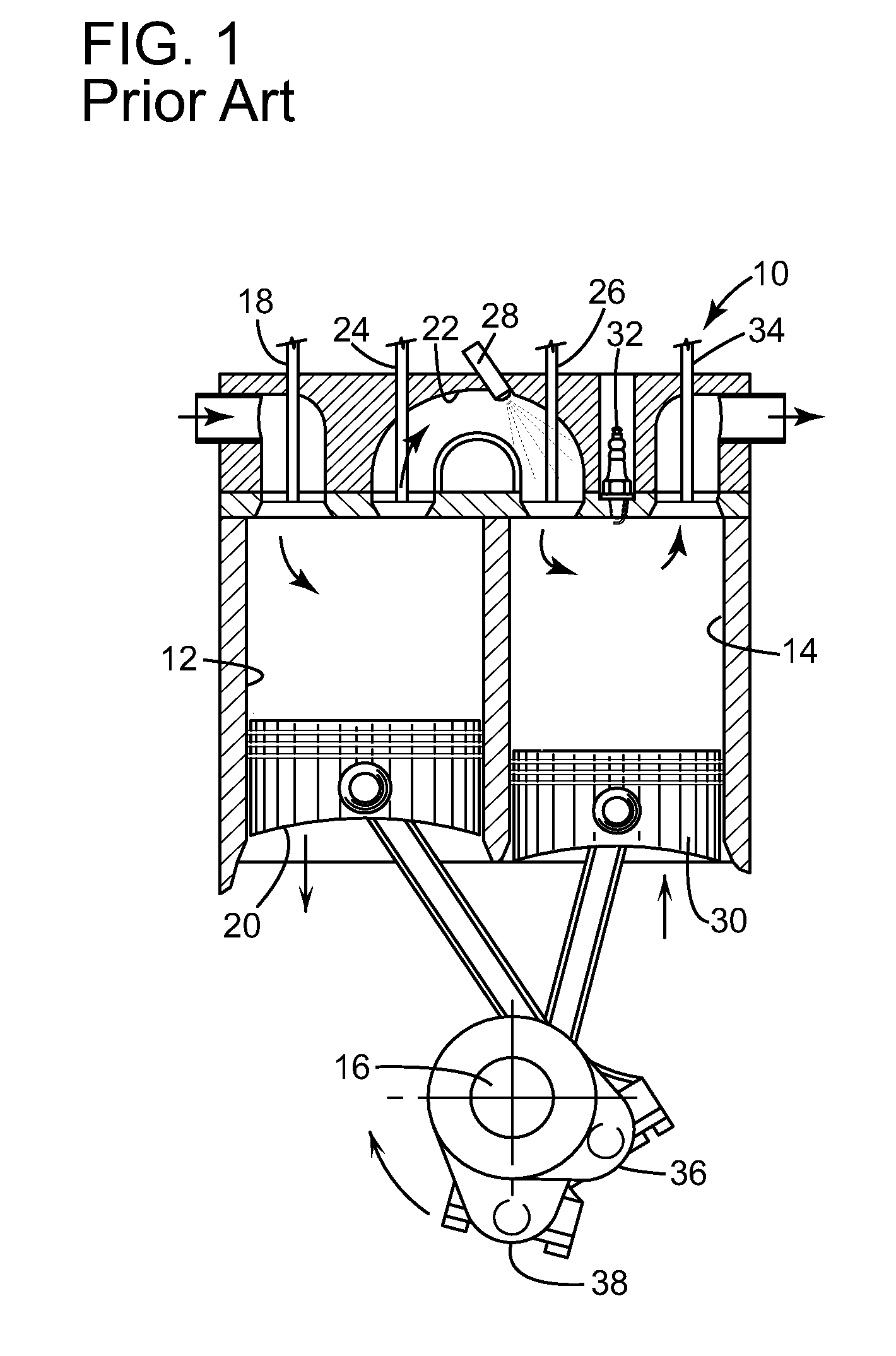
[0055]Referring to FIG. 5, numeral 100 generally indicates a diagrammatic representation of an exemplary embodiment of a split-cycle engine according to the present invention. Engine 100 includes a crankshaft 102 rotatable about a crankshaft axis 104 in a clockwise direction as shown in the drawing. The crankshaft 102 includes adjacent angularly displaced leading and following crank throws 106, 108, connected to connecting rods 110, 112, respectively.

[0056]Engine 100 further includes a cylinder block 114 defining a pair of adjacent cylinders, in particular a compression cylinder 116 and an expansion cylinder 118 closed by a cylinder head 120 at one end of the cylinders opposite the crankshaft 102. A compression piston 122 is received in compression cylinder 116 and is connected to the connecting rod 112 for reciprocation of the piston 122 between top dead center (TDC) and bottom dead center (BDC) positions. An expansion piston 124 is received in expansion cylinder 118 and is connect...


PUM


Abstract

The present invention provides a valve actuation system comprising a valve train for actuating a valve, the valve train including actuating elements and a valve lash, and a valve lash adjustment system for adjusting the valve lash, wherein the valve train and the valve lash adjustment system do not share any common actuating elements.

Description

[0001]This application is a Continuation of U.S. application Ser. No. 12 / 690,514 filed on Jan. 20, 2010, to which priority under 35 U.S.C. §120 is claimed. U.S. application Ser. No. 12 / 690,514 claims priority under 35 U.S.C. §119(e) to U.S. Provisional Application No. 61 / 205,777 filed on Jan. 22, 2009, the entire content of which is incorporated herein by reference.TECHNICAL FIELD[0002]The present invention relates generally to a valve lash adjustment system and a valve actuation system for a valve of an internal combustion engine. More specifically, the present invention relates to a valve lash adjustment system for a valve of a split-cycle engine.BACKGROUND OF THE INVENTION[0003]For purposes of clarity, the term “conventional engine” as used in the present application refers to an internal combustion engine wherein all four strokes of the well known Otto cycle (the intake, compression, expansion and exhaust strokes) are contained in each piston / cylinder combination of the engine. ...

Claims


Application Information

Patent Timeline
Patent Type & Authority Patents(United States)
IPC IPC(8): F01L1/18
CPCF01L1/185F01L1/22F01L1/2405F02B33/22F01L1/08F01L2003/258Y10T74/2107F01L2101/00F01L2301/00F01L1/18F01L1/20
Inventor MELDOLESI, RICCARDOLACY, CLIVEPERKINS, ANTHONYGILBERT, IAN
Owner SKADERI GRUP LLC
Why Eureka
Try Eureka