Blade control system and construction machine

a control system and construction machine technology, applied in mechanical machines/dredgers, analogue processes for specific applications, instruments, etc., can solve the problems of inability to appropriately transfer the driving force of the drive unit to the ground, the cutting edge of the blade excessively dozing the object across the designed surface, and the difficulty of operators to accurately grasp suitable timing

Active Publication Date: 2013-10-01
KOMATSU LTD
View PDF17 Cites 16 Cited by
  • Summary
  • Abstract
  • Description
  • Claims
  • Application Information

AI Technical Summary

Benefits of technology

[0009]According to the blade control system of the first aspect of the present invention, the grading control is configured to be switched into the dozing control when the distance between the designed surface and the cutting edge of the blade is greater than the first distance, then it is possible to inhibit excessive shoe slippage due to excessive blade load. By contrast, the dozing control is configured to be switched into the grading control when the distance between the designed surface and the cutting edge of the blade is less than the second distance, then it is possible to inhibit excessive dozing due to the cutting edge of the blade shoved across the designed surface into an object for dozing. It is thus possible to simultaneously achieve inhibition of excessive shoe slippage and inhibition of excessive dozing by the appropriate automatic switching between the grading control and the dozing control.
[0012]According to the blade control system of the second aspect of the present invention, the grading control and the dozing control are switched back and forth in accordance with the blade load when the distance between the designed surface and the cutting edge of the blade falls in a range from the second distance to the first distance. Specifically, when the blade load is small, the grading control is configured to be executed for preventing the cutting edge of the blade from being shoved across the designed surface into an object for dozing, because a large amount of soil can be held when the blade load is small. By contrast, when the blade load is large, the dozing control is configured to be executed, because excessive shoe slippage may result in rough road surface and degradation in operation efficiency when the blade load is large. Put the above together, it is possible to further enhance operation efficiency in addition to inhibition of excessive shoe slippage and inhibition of excessive dozing.
[0014]According to the blade control system of the third aspect of the present invention, it is possible to inhibit excessive switching between the dozing control and the grading control, then it is possible to reduce load acting on a hydraulic system.
[0020]Overall, according to the present invention, it is possible to provide a blade control system and a construction machine for appropriately executing automatic switching between a grading control and a dozing control.

Problems solved by technology

However, it is difficult for operators to accurately grasp suitable timing for switching between a grading control and a dozing control.
When the timing of switching from the dozing control to the grading control is too late, on the other hand, the cutting edge of the blade excessively dozes the object across the designed surface.
It should be noted that the excessive shoe slippage herein refers to a state that driving force of the drive unit cannot be appropriately transferred to the ground due to an excessively increased amount of slippage of the tracks of a drive unit against the ground.
By contrast, when the blade load is large, the dozing control is configured to be executed, because excessive shoe slippage may result in rough road surface and degradation in operation efficiency when the blade load is large.

Method used


Image

  • Blade control system and construction machine
  • Blade control system and construction machine
  • Blade control system and construction machine

Examples


Embodiment Construction

[0033]Selected embodiments will now be explained with reference to the drawings. It will be apparent to those skilled in the art from this disclosure that the following descriptions of the embodiments are provided for illustration only and not for the purpose of limiting the invention as defined by the appended claims and their equivalents.

[0034]With reference to attached figures, a bulldozer will be hereinafter explained as an exemplary “construction machine”. In the following explanation, the terms “up”, “down”, “front”, “rear”, “right” and “left” and their related terms should be understood as directions seen from an operator seated on an operator's seat.

Overall Structure of Bulldozer 100

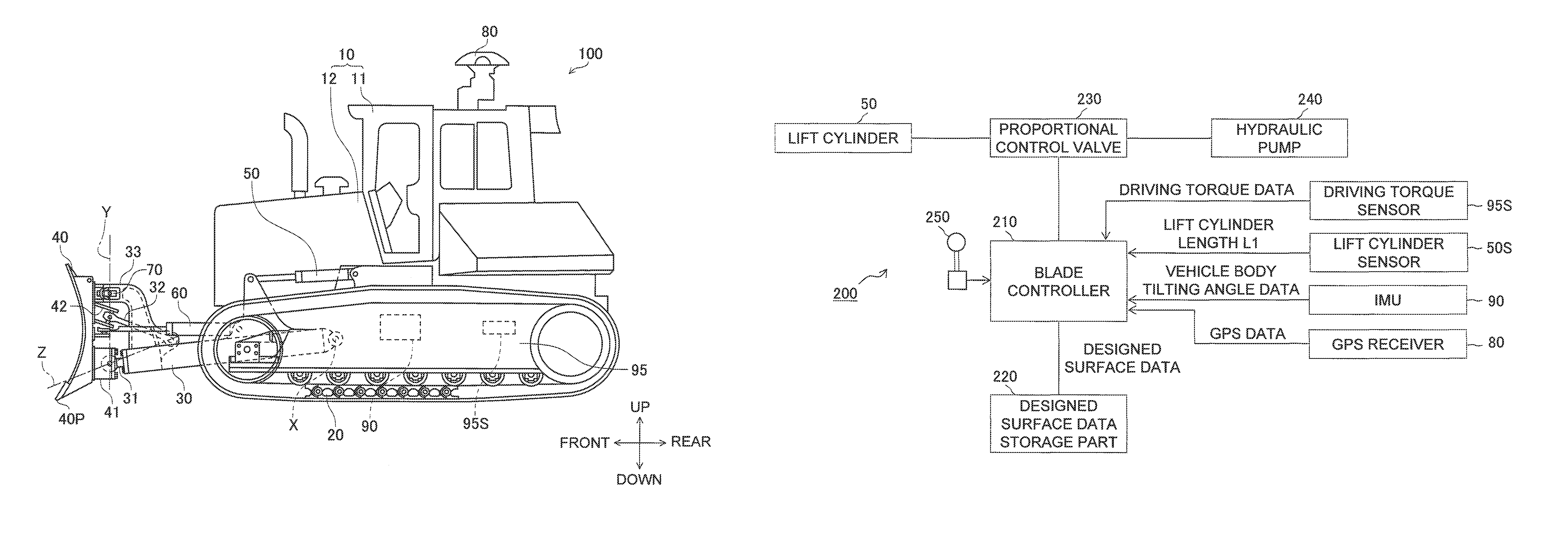
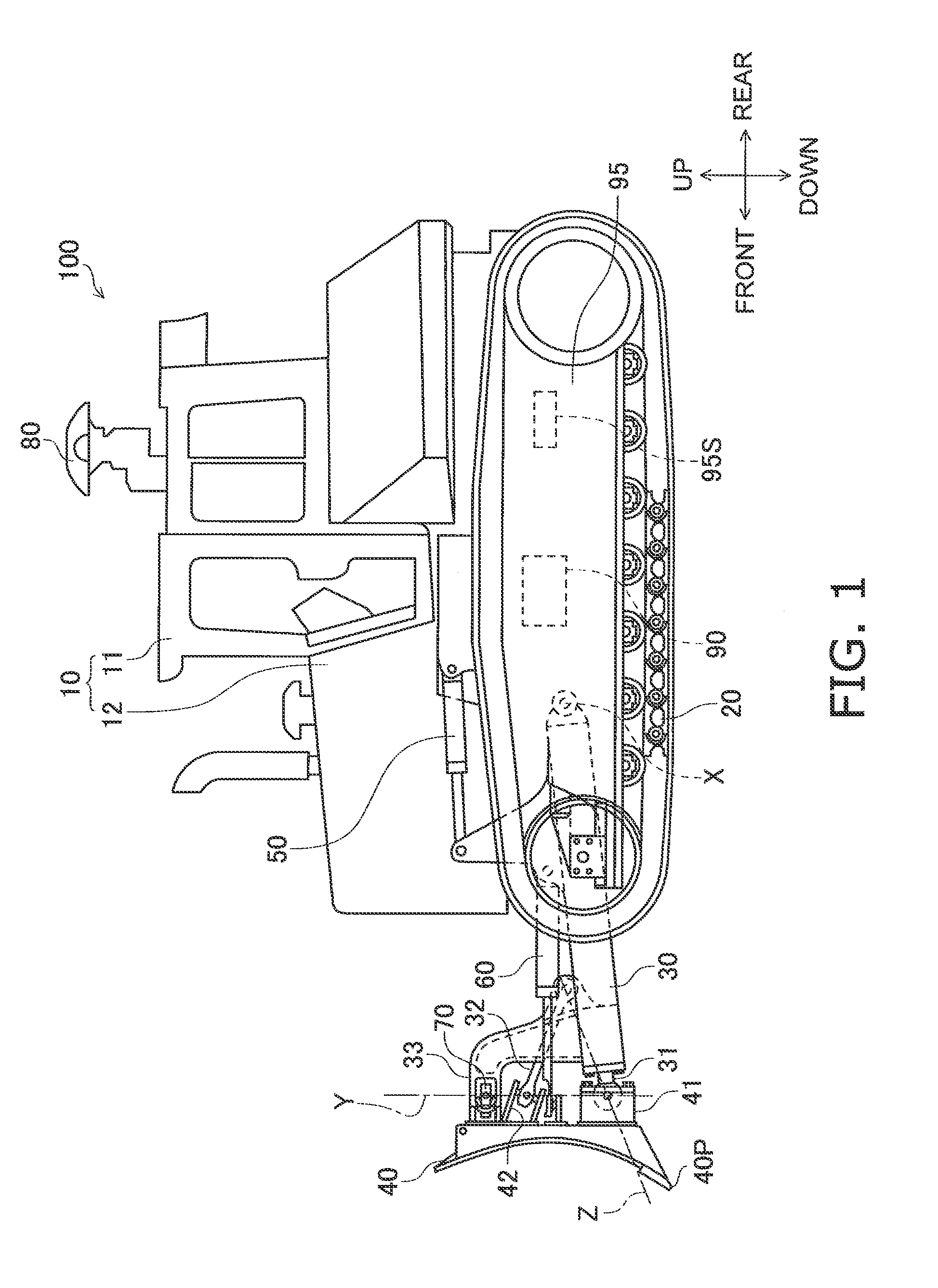
[0035]FIG. 1 is a side view of the entire structure of a bulldozer 100 according to an exemplary embodiment of the present invention.

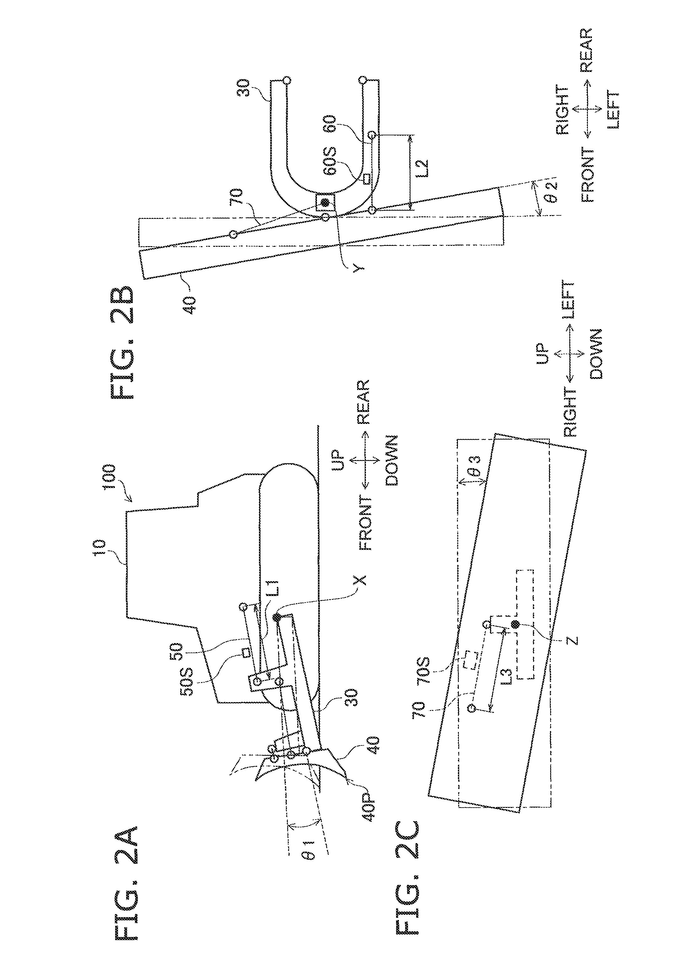
[0036]The bulldozer 100 includes a vehicle body 10, a drive unit 20, a lift frame 30, a blade 40, a lift cylinder 50, a angling cylinder 60, a tilt cylinder 70, a G...


PUM


Abstract

A blade control system of the present invention includes a distance calculating part, a blade load obtaining part and a lift cylinder controlling part. The distance calculating part is configured to obtain distance between a designed surface and a cutting edge of a blade. The blade load obtaining part is configured to obtain blade load acting on the blade. The lift cylinder controlling part is configured to execute a dozing control when the aforementioned distance is greater than a first distance. Further, the lift cylinder controlling part is configured to execute a dozing control when the aforementioned distance is less than a second distance.

Description

BACKGROUND OF THE INVENTION[0001]1. Technical Field[0002]The present invention relates to a blade control system and a construction machine for causing a cutting edge of a blade to move across a designed surface.[0003]2. Description of the Related Art[0004]Well-known dozing controls, having been proposed for the construction machines (e.g., bulldozers and graders), are configured to automatically adjust the vertical position of a blade for causing a cutting edge of the blade to move across a designed surface indicating a target contour of an object for dozing (see e.g., Japan Laid-open Patent Application Publication No. JP-A-H11-256620).[0005]Meanwhile, well-known dozing controls, having been proposed for the construction machines, are configured to automatically adjust the vertical position of a blade for causing a load of a target level to act on the blade (see e.g., Japan Laid-open Patent Application Publication No. JP-A-H05-106239).SUMMARY[0006]However, it is difficult for opera...

Claims


Application Information

Patent Timeline
Patent Type & Authority Patents(United States)
IPC IPC(8): E02F3/76
CPCE02F3/847
Inventor HAYASHI, KAZUHIKO
Owner KOMATSU LTD
Why Eureka
Try Eureka