
Hollow fiber membrane and method for manufacturing thereof

a hollow fiber membrane and fiber technology, applied in the field of semi-permeable hollow fiber membranes, can solve problems such as space for improvement and optimization

Active Publication Date: 2013-12-03
GAMBRO LUNDIA AB
View PDF32 Cites 10 Cited by
  • Summary
  • Abstract
  • Description
  • Claims
  • Application Information

AI Technical Summary

Benefits of technology

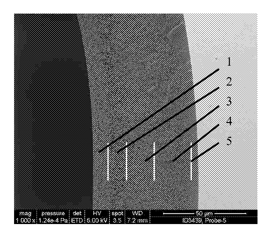
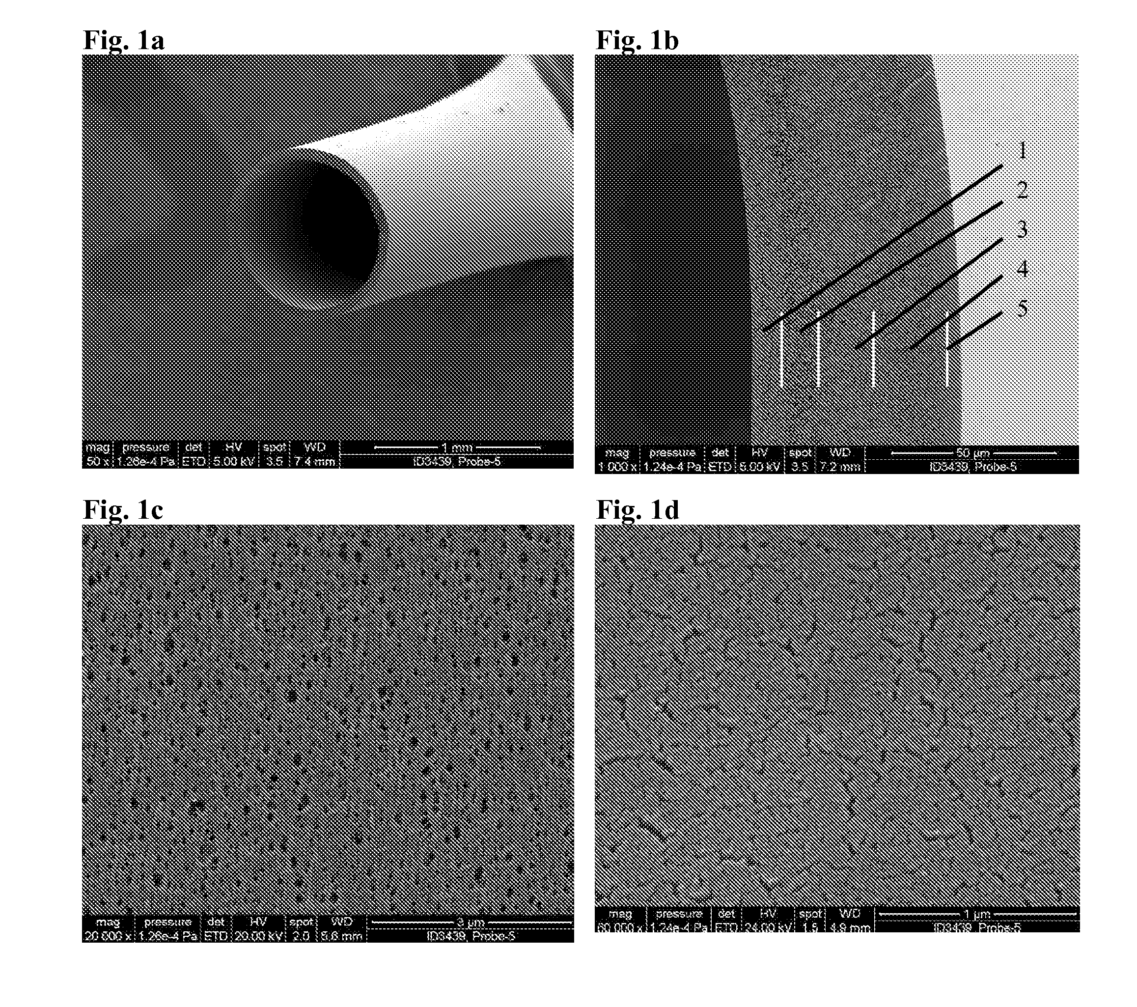
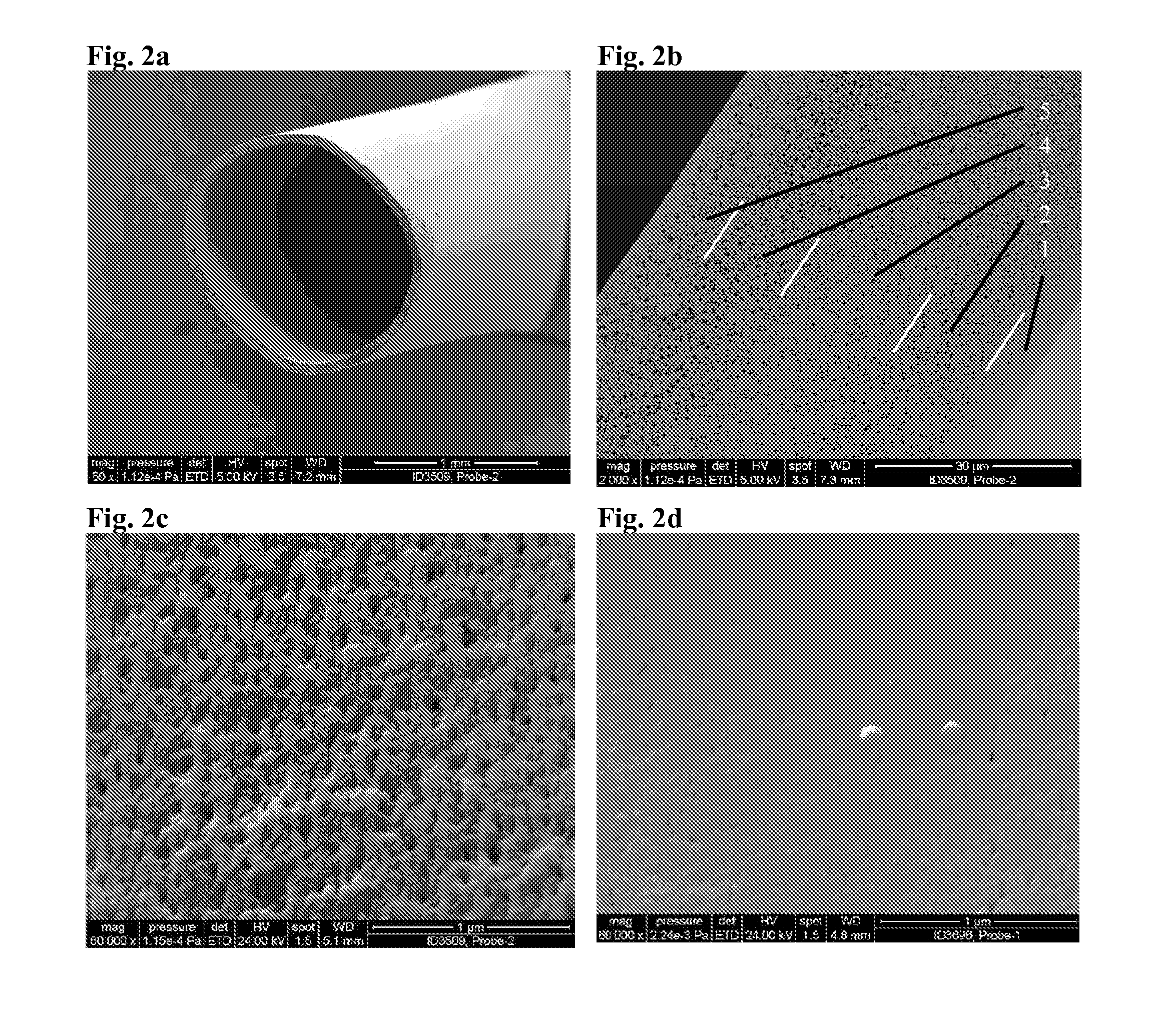
[0009]Ra=1N⁢∑i=1N⁢ZiRq=1N⁢∑i=1N⁢Zi2with N being the total number of data points and Zi being the height of a data point above the average picture level. With this smooth outer surface, the combination of the polymer system used and the membrane formation conditions, low thromboginicity of the membrane is achieved. The extremely smooth surface does inhibit haemolysis if used in direct blood contact. Blood cells will not be ruptured during the contact with the smooth surface. The smoothness further reduces the interaction with proteins and the adsorption of proteins on the outer surface of the hollow fiber membrane.
[0052]The porous structure behind the “selective” outer surface in direction to the lumen side has larger pores up to several μm. The porous structure is gained by a slow phase separation process. To allow a slow phase separation process the amount of a solvent (solvent for the polymer) has to be sufficient high. However, high concentration of a solvent in the bore liquid (could also be called the center fluid, which is introduced in the bore or center of the hollow fiber during the precipitation procedure) and the precipitation bath creates instability of the fiber. This makes it difficult to get stable fibers into the precipitation bath and out of this bath. The challenge is to adjust the solvent concentration during the precipitation procedure (in the center and the precipitation bath) and the precipitation bath temperature in such a way that it allows the creation of a membrane that has smaller pores on the outer surface than on the inner surface in addition with a very smooth outer surface for good biocompatibility.

Problems solved by technology

The membranes according to prior art are well performing, but still have some space for improvement and optimization.
One limiting feature of these membranes are that the fluid to be filtered is intended to flow in the interior lumen of the hollow fiber and the filtrate to go through the fiber wall from the lumen side to the outer wall side.

Method used


Image

  • Hollow fiber membrane and method for manufacturing thereof
  • Hollow fiber membrane and method for manufacturing thereof
  • Hollow fiber membrane and method for manufacturing thereof

Examples


example 1

[0113]A polymer solution is prepared by dissolving polyethersulphone (BASF Ultrason 6020) and polyvinylpyrrolidone (PVP) (BASF K30 and K85) in N-methylpyrrolidone (NMP). The weight fraction of the different components in the polymer spinning solution was: PES-PVP K85-PVP K30-NMP: 18-3.25-8-70.75. The viscosity of the polymer solution was 53560 mPa×s.

[0114]To prepare the solution NMP is first filled into a three neck-flask with finger-paddle agitator in the center neck. The PVP is added to the NMP and is stirred at 50° C. until a homogeneous clear solution is prepared. Finally, the polyethersulphone (PES) is added. The mixture is stirred at 50° C. until a clear high viscous solution is obtained. The warm solution is cooled down to 20° C. and degassed. To fully degas the solution, the highly viscous polymer solution is transferred into a stable stainless steel container. Thereafter the container is closed tightly and vacuum is applied to the container. The solution is degassed at 50 m...

example 2

[0118]The second example has been carried out with the identical composition of the polymer solution as in Example 1. The viscosity of the polymer solution was 60200 mPa×s.

[0119]The polymer preparation procedure was kept as described in Example 1. The membrane formation procedure was changed for the following points:

[0120]

Temperature of the spinning nozzle:54°C.Spinning velocity:7.5m / minDistance between the spinning nozzle2.5cmand the precipitation bath:Temperature of the precipitation bath:27°C.

[0121]The remaining process steps are kept as in example 1. The wet hollow fiber membrane has an inner diameter of 1464 μm, an outer diameter of 1592 μm and a fully asymmetric membrane structure. The active separation layer of the membrane is at the outer wall surface. The active separation layer is defined as the layer with the smallest pores. The hydraulic permeability (Lp value) of the membrane is measured from inside to outside in a hand bundle, using the methods described earlier. The m...

example 3

[0124]The third example has been carried out with the identical composition of the polymer solution as in Example 1. The viscosity of the polymer solution was 59300 mPa×s.

[0125]The polymer preparation procedure was kept as described in Example 1. The membrane formation procedure was changed for the following points:

[0126]

Bore liquid (H2O:NMP)38 wt.-%:62 wt.-%Concentration of NMP in the precipitation bath:64wt.-%Distance between the spinning nozzle and3cmthe precipitation bath:Temperature of the precipitation bath:22°C.

[0127]The remaining process steps are kept as in Example 1. The only difference is that the fiber had different dimensions. The hollow fiber membrane has an inner diameter of 203 μm, an outer diameter of 281 μm and a fully asymmetric membrane structure. The active separation layer of the membrane is at the outer wall surface. The active separation layer is defined as the layer with the smallest pores. The hydraulic permeability (Lp value) of the membrane is measured fr...


PUM

PropertyMeasurementUnit
roughnessaaaaaaaaaa
inner diameteraaaaaaaaaa
thicknessaaaaaaaaaa

Abstract

The present invention concerns a semipermeable hollow fiber membrane having an outer wall surface, an inner wall surface and an interior lumen extending along the length thereof and having the selective layer on the outer wall surface with a surface roughness below 10 nm. According to the invention the membrane has the smallest pore size on the outer wall surface, and has an outer wall surface which is smooth, continuous and homogeneous in a nanoscopic scale and four to five distinct layers of different pore size and density. Further the present invention concerns a process for manufacturing thereof and the use thereof.

Description

CROSS REFERENCE TO RELATED APPLICATIONS[0001]This application is a national phase application based on PCT / EP2007 / 060838, filed Oct. 11, 2007, which claims the priority of Swedish Patent Application No. 0602189-3, filed Oct. 18, 2006; and claims the benefit of U.S. Provisional Application No. 60 / 829,965, filed Oct. 18, 2006, the contents of all of which are incorporated herein by reference.TECHNICAL FIELD[0002]The present invention concerns a semi-permeable hollow fiber membrane having an outer wall surface, an inner wall surface and an interior lumen extending along the length thereof. More particular it relates to a membrane having the selective layer on the outer wall surface.BACKGROUND OF THE INVENTION[0003]Semi-permeable hollow fiber membranes are known in detail in, for example, EP-A-0 568 045, EP-A-0 168 783, EP-B-0 082 433, WO 86 / 00028, and EP 0 824 960. These membranes are manufactured from polymeric synthetic materials, they have asymmetric structure with high diffusive pe...

Claims


Application Information

Patent Timeline
Patent Type & Authority Patents(United States)
IPC IPC(8): B01D69/08B01D69/12D01D5/24D01F1/08
CPCB01D63/02B01D69/02B01D69/08B01D69/087B01D71/44B01D71/68A61M1/16B01D2323/06B01D2323/08B01D2323/12B01D2323/22B01D2325/022A61B5/14525B01D71/62
Inventor KRAUSE, BERNDGOHL, HERMANNHORNUNG, MARKUSZWEIGART, CARINA
Owner GAMBRO LUNDIA AB
Learn More