
Sewing machine having a camera for forming images of a sewing area

a sewing machine and camera technology, applied in the field of sewing machines, can solve the problems of no method and adherent devices, cannot, of course, be used on fabrics, and may be difficult to place embroidery or seams in question in such a desired position

Active Publication Date: 2013-12-10
SINGER SOURCING LTD LLC
View PDF206 Cites 18 Cited by
  • Summary
  • Abstract
  • Description
  • Claims
  • Application Information

AI Technical Summary

Benefits of technology

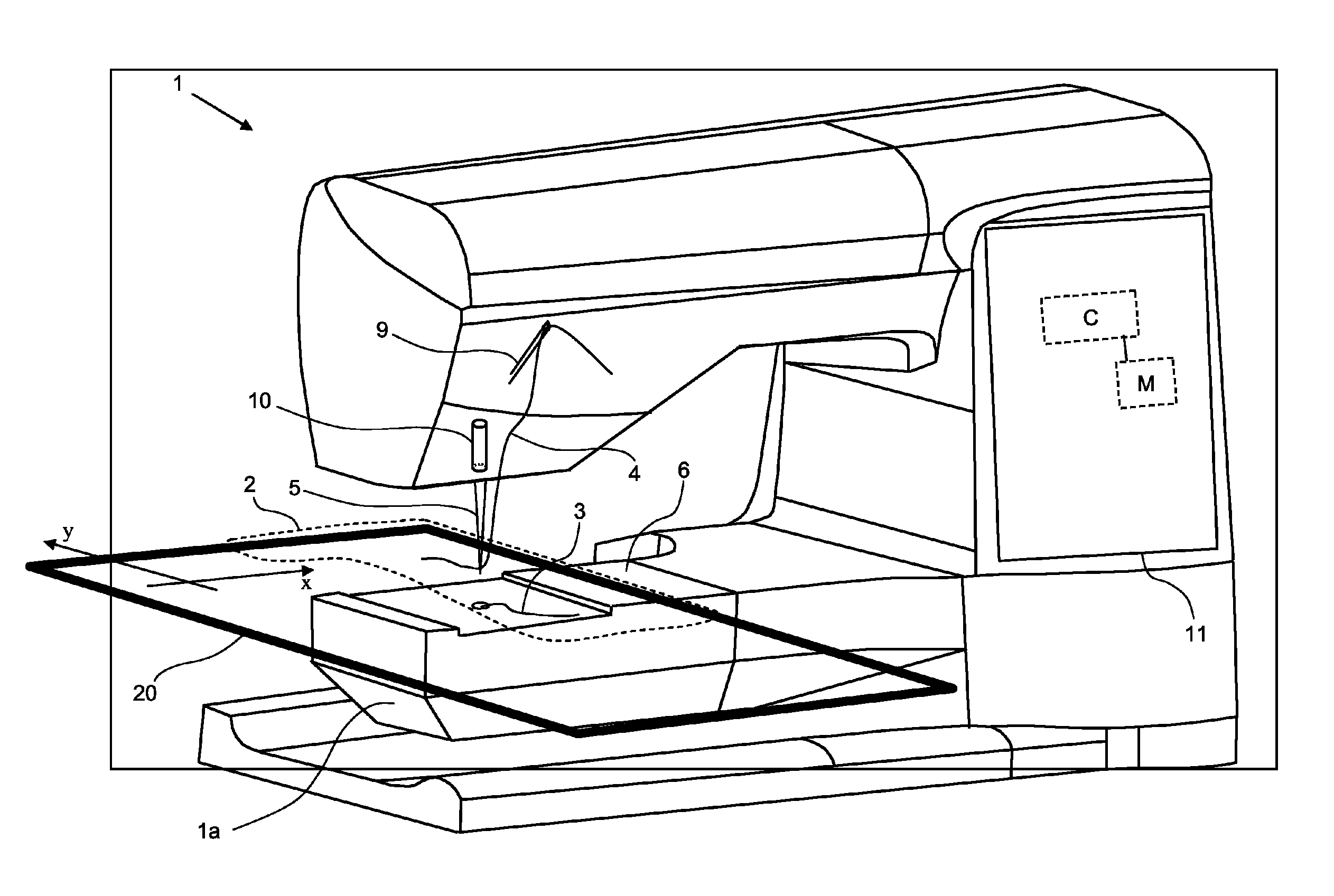
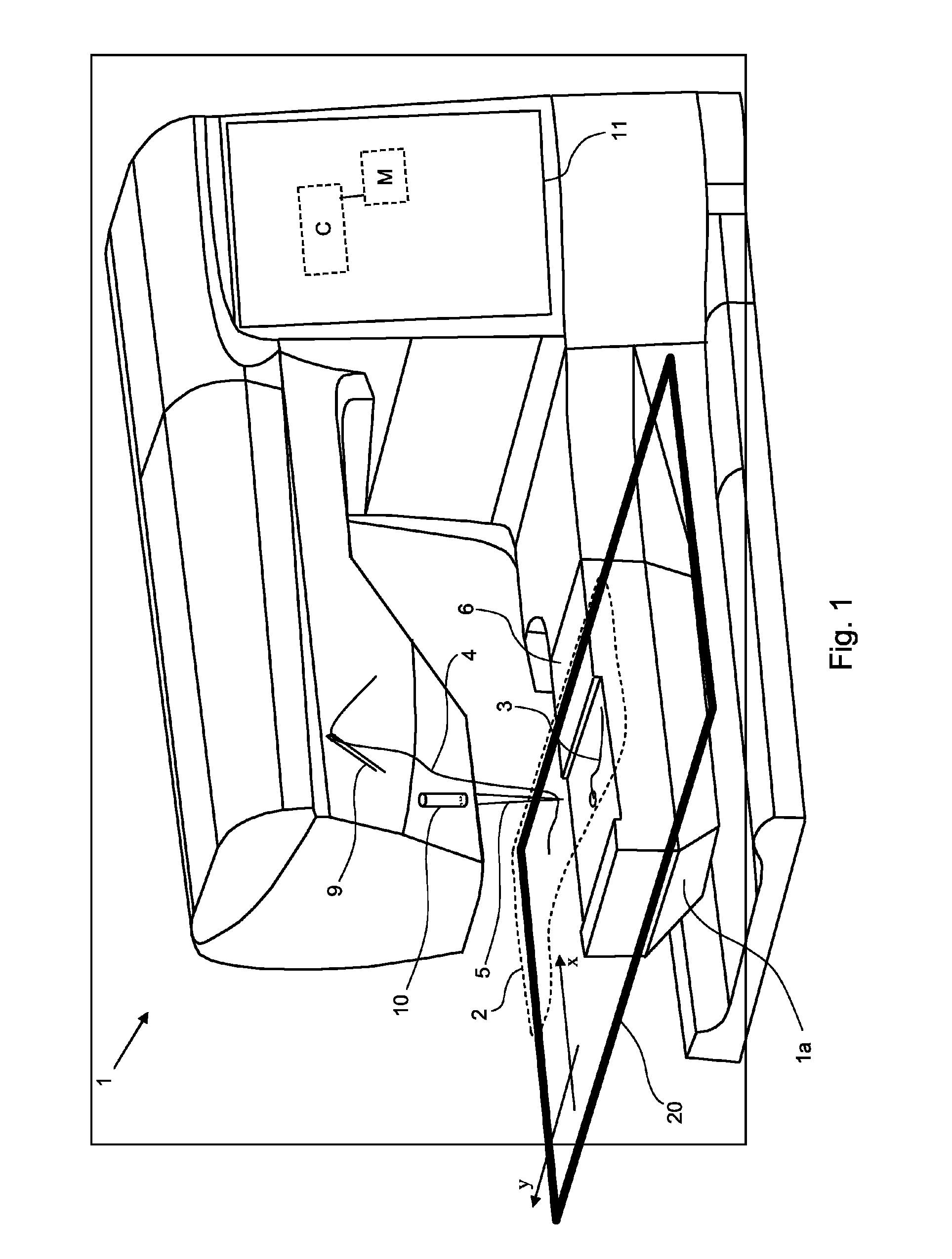
The present invention provides a sewing machine with a built-in camera that can be used to coordinate predetermined positions on a fabric, such as for seams or embroidery elements. The camera is small and unobtrusive, and can be easily integrated into the sewing machine. The technical effect is the simplification and enhancement of sewing processes through the use of a visual system.

Problems solved by technology

Positioning the embroidery or seam in question in such a desired position may be difficult, especially if such an adaptation is desired with very high precision.
Other issues of interest when using a hoop is, e.g. for a user to have an idea about how parts of an embroidery are related to each other.
A drawback in the use of sewing machines provided with a display is that no method and adherent devices exist to show on the display an undistorted picture of the full work area such as, for example, the work area of a fabric clamped in a hoop.
A disadvantage of such a method is that it cannot, of course, be used on fabrics that have not been provided initially with pre-print containing position determinations.

Method used


Image

  • Sewing machine having a camera for forming images of a sewing area
  • Sewing machine having a camera for forming images of a sewing area
  • Sewing machine having a camera for forming images of a sewing area

Examples


Embodiment Construction

[0008]It is an object of the present invention to present a method and a device for providing in a sewing machine an image of a sewing area of a fabric, wherein the coordinates of the image refer to corresponding coordinates of the sewing area.

[0009]It is a further object of the present invention to suggest a method and a device for coordinating predetermined positions in a simple manner, for example positions for seams or embroidery elements on a fabric, with corresponding positions stored in an electronic memory for display on a screen.

[0010]According to the objects of the invention there is provided a sewing machine with a vision system, which consists of a normal embroidery machine with a small built-in camera that is used for different purposes simplifying and enhancing the sewing. The camera is as small as possible, built-in, e.g., to an extent where it is barely noticeable.

[0011]According to one aspect of the invention, a method is presented which has the characteristic featu...


PUM


Abstract

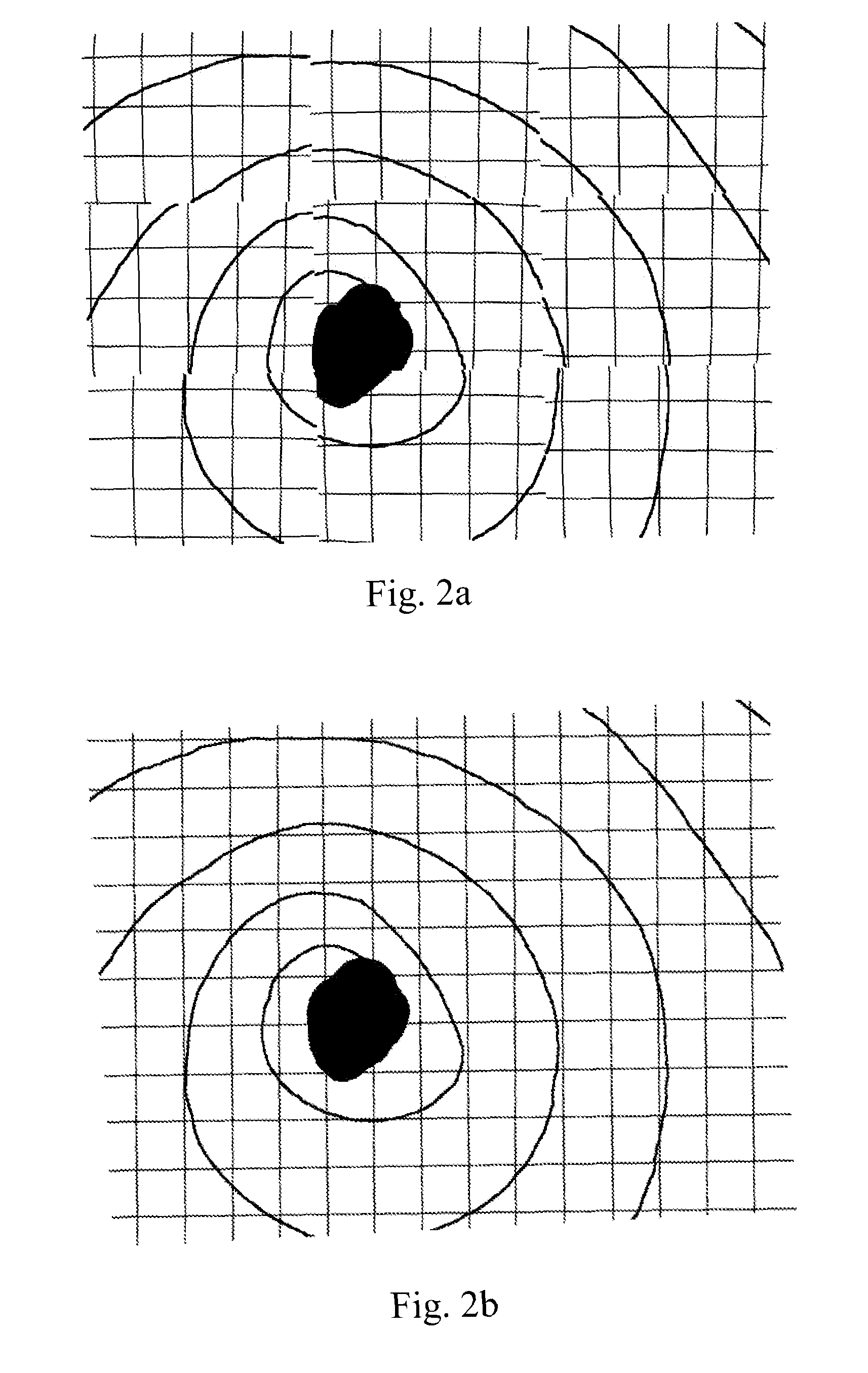
A sewing machine (1) has access to a memory (M) for stitch data and a processor (C) for reading said stitch data and for operating the sewing machine (1) to execute stitches according to stitch data, wherein the sewing machine (1) has a hoop (20) for framing a pattern of the sewing material (2), and for moving the framed pattern in a direction comprising a component of at least one of a first coordinate (x) and a second coordinate (y) and wherein further the processor (C) controls movements of the hoop (20) according to said direction in relation to the position of a needle (5) of the sewing machine and synchronously with the movement of the needle for executing stitches, wherein: —the stretched sewing material (2) is clamped to the hoop (20) for forming a framed pattern in the hoop, —the framed pattern of the sewing material (2) is scanned by means of a camera (10) mounted in the sewing machine (1) and directed towards the sewing material (2) for the purpose of taking pictures of part views of said framed pattern, —said part views are tiled together for forming on a display an image of the pattern framed in the hoop, whereby a coordinate of the image of a display (11) refers to a corresponding coordinate of the pattern framed in the hoop (20).

Description

TECHNICAL FIELD[0001]The present invention relates to a sewing machine provided with a camera. The camera is used for forming images of a sewing area. The invention is also directed to the method for providing said images and to applications of said method to facilitate sewing.BACKGROUND ART[0002]It is known that embroideries can be executed by means of a sewing machine, wherein the embroidery is stored in a memory that contains stitch data for the embroidery. An operator selects, for example, an embroidery from the memory and places a sewing material, on which the embroidery is to be executed, stretched or clamped onto an embroidery hoop [hereinafter referred to as “hoop” only] which is arranged in the sewing machine in such a way that a control program for the sewing machine mechanically moves the hoop in accordance with a control program and stitch data when executing the embroidery on the sewing material. The sewing material is usually a fabric, which concept will be used herein...

Claims


Application Information

Patent Timeline
Patent Type & Authority Patents(United States)
IPC IPC(8): D05C5/02
CPCD05B19/10D05B19/12D05C9/06D05D2205/16
Inventor HJALMARSSON, ANDERSBONDESSON, CHRISTIANFLYGARE, ANDERSCRONA, BJORN
Owner SINGER SOURCING LTD LLC
Learn More