Sliding T bevel with digital readout

a technology of digital readout and slide, which is applied in the direction of measuring gauges, printing, writing aids, etc., can solve the problems of inconvenient operation and difficulty in obtaining the degree of accuracy desired for angle measuremen

Active Publication Date: 2013-12-17
GEN TOOLS & INSTR
View PDF21 Cites 29 Cited by
  • Summary
  • Abstract
  • Description
  • Claims
  • Application Information

AI Technical Summary

Problems solved by technology

This is sometimes inconvenient to accomplish.
Further, when using a mechanical type protractor it is sometimes difficult to obtain an angle measurement with the degree of accuracy desired, such as to one tenth of a degree.
However, this still requires the purchase and use of two tools.

Method used


Image

  • Sliding T bevel with digital readout
  • Sliding T bevel with digital readout
  • Sliding T bevel with digital readout

Examples


Embodiment Construction

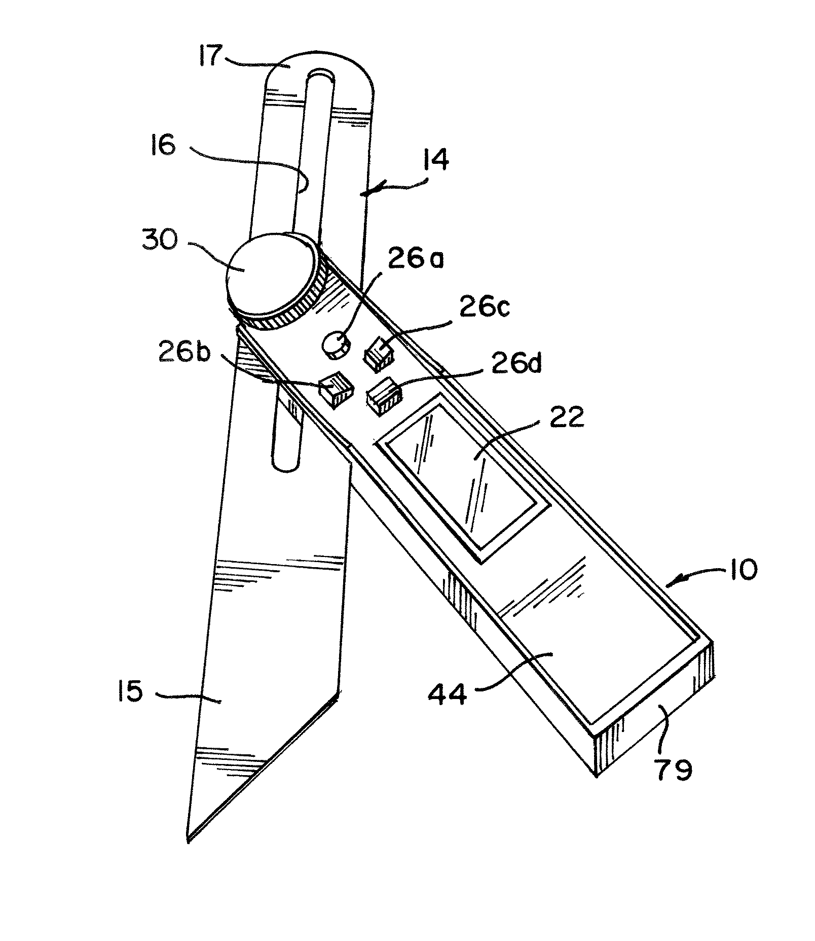
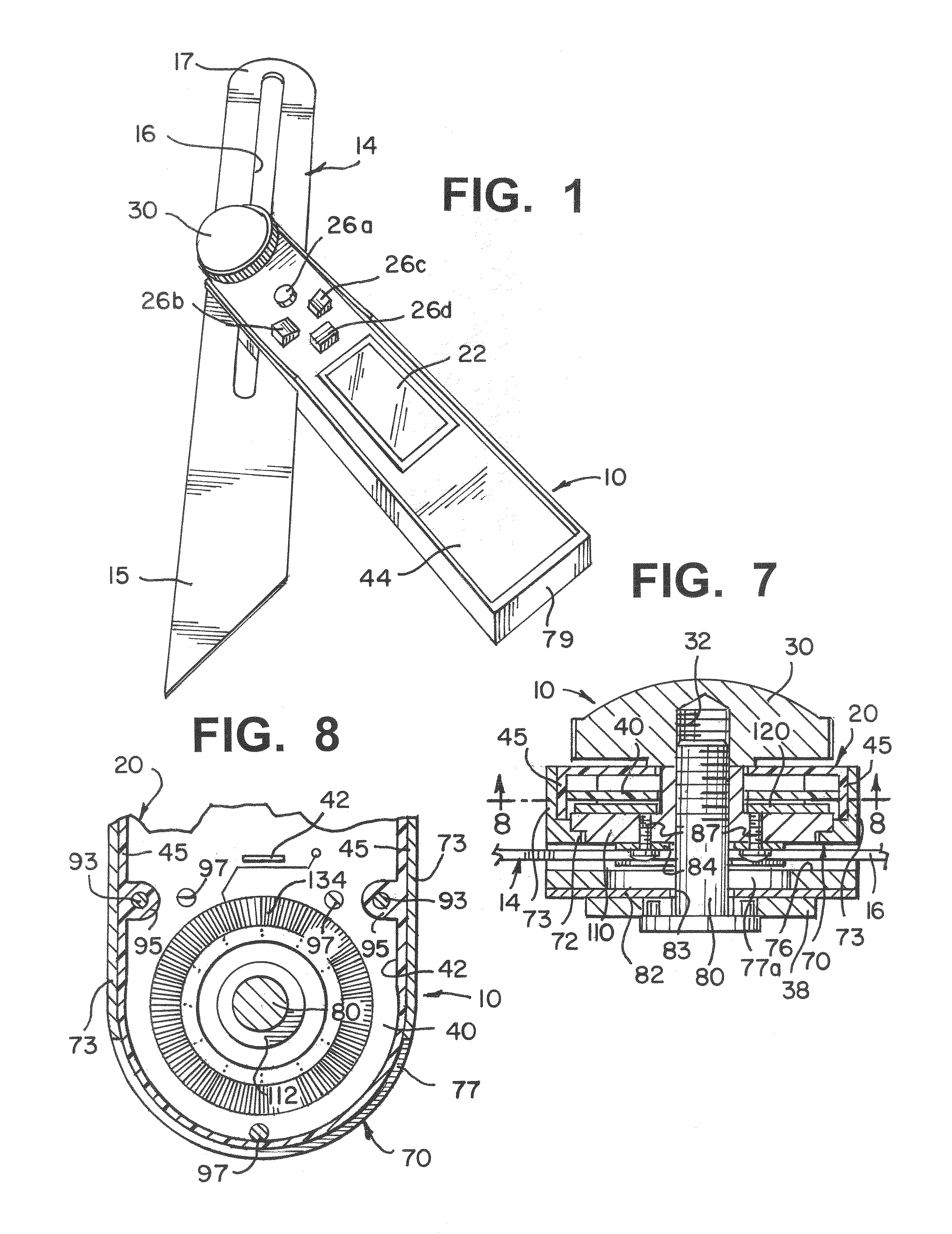
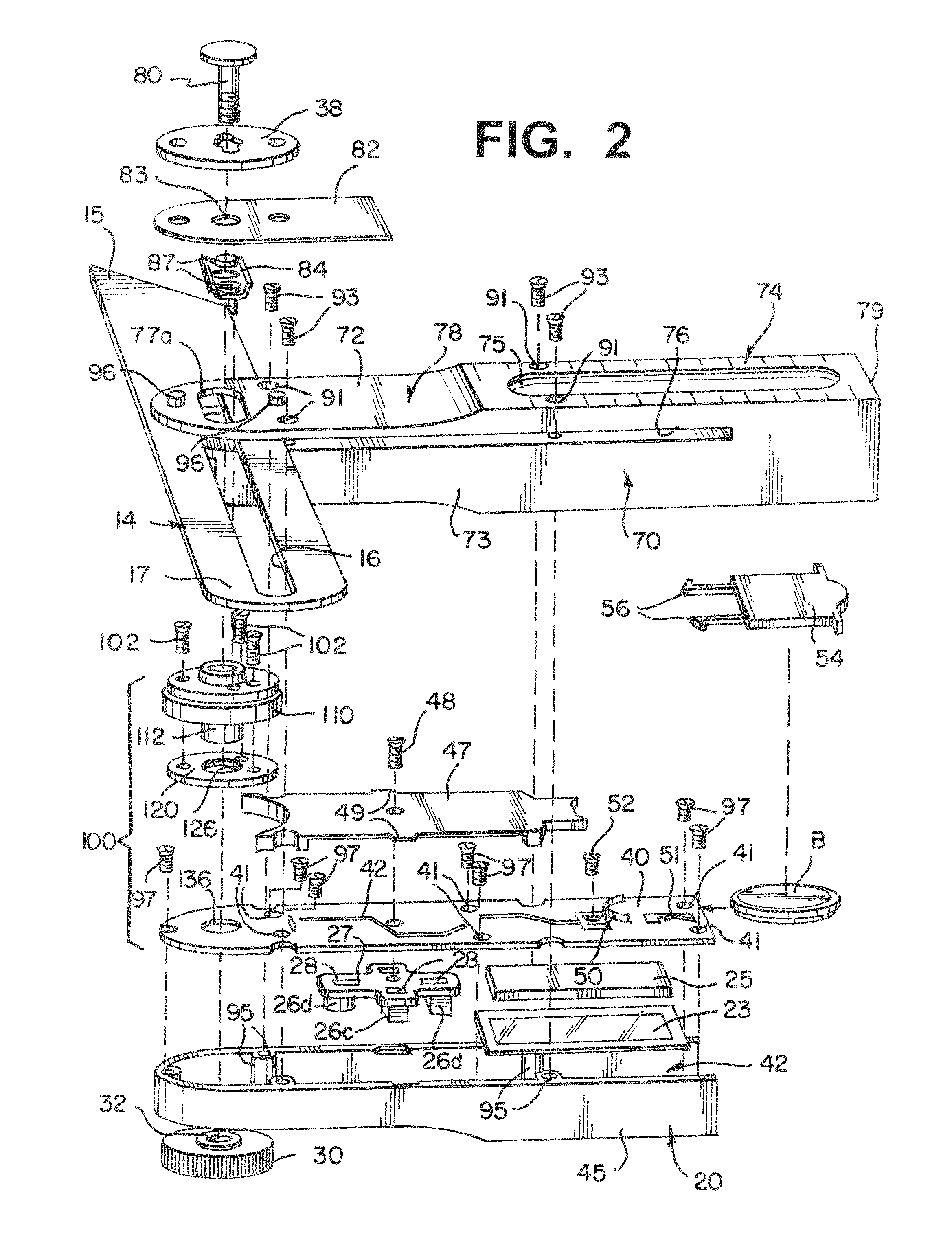
[0016]Referring to FIGS. 1 and 2, the sliding digital T bevel of the invention has two main parts. There is an elongated blade 14 with an angled and pointed front end 15 and a close curved rear end 17. The blade 14 is of a rigid material, such as stainless steel. The blade has an elongated slot 16 from near the midpoint that extends to near the blade curved rear end 17.

[0017]A rectangular shaped handle 10 is to slide along the length of the blade slot 16 and to be pivoted to an angle relative to the blade longitudinal axis. A control knob 30 on the upper side of the handle locks the handle along the blade length and at the angle to which it has been pivoted. As explained in greater detail below, the control knob 30 is associated with electronic apparatus that determines the angle to which the handle has been pivoted relative to the blade longitudinal axis. The handle includes a digital display 22, which numerically displays the angle to which the handle has been rotated relative to ...


PUM


Abstract

A digital T-bevel has a blade with a slot along a part of its length and a handle having an end that is mounted both to move along the length of the slot and to pivot with respect to the blade longitudinal axis. The handle also includes an encoder to measure the angle of the handle relative to the blade longitudinal axis and the necessary electronic circuitry to convert the measured angle into digital form to drive a display to visually display the numerical value of the measured angle.

Description

BACKGROUND OF THE INVENTION[0001]A sliding T bevel is an adjustable gauge for setting and transferring angles. The bevel has two main parts. There is an elongated blade, usually of metal, that has a slot along most of its length. There also is a swivel arm or handle, usually made of wood or plastic, which is connected is connected to the blade by a bolt that passes through the slot and which has a thumbscrew or wing nut. Upon loosening the thumbscrew the handle is positioned along the slot length and pivoted to an angle relative to the blade longitudinal axis. It is then locked in this position by tightening the thumbscrew.[0002]Sliding T bevels are mostly used for measuring or transferring angles to be duplicated, such as the angle of the cut at the end of a board. In use, the blade is placed against the long edge of the board being measured and the thumbscrew is rotated to unlock the handle. While, the blade is held to the board edge the handle is moved to lie against the cut angl...

Claims


Application Information

Patent Timeline
Patent Type & Authority Patents(United States)
IPC IPC(8): B43L7/10
CPCG01B3/56
Inventor EDWARDS, CHRISTOPHER L.
Owner GEN TOOLS & INSTR
Why Eureka
Try Eureka