
Imaging apparatus and imaging method

a technology which is applied in the field of imaging apparatus and imaging method, can solve the problems of display quality level decreasing by an increase, the inability to perform the finder function as a camera, and the inability to follow the capability of the camera, so as to reduce reduce the release time lag, and increase the frame rate of monitoring.

Inactive Publication Date: 2013-12-17
RICOH KK
View PDF12 Cites 0 Cited by
  • Summary
  • Abstract
  • Description
  • Claims
  • Application Information

AI Technical Summary

Benefits of technology

[0011]An object of the present invention is to provide an imaging apparatus and an imaging method capable of reducing a release time lag by heightening a frame rate for monitoring when a monitoring stop processing to stop a transfer of a digital image signal from an analog image processing device and an image processing of a digital image processing device is performed in a photographing sequence, even if the frame rate for the monitoring is lowered for power saving and so on.

Problems solved by technology

However, according to the above-mentioned techniques described in Japanese Patent Laid-Open Publication Numbers 2007-104564, 2003-92698, and 2003-60994, while power saving can be achieved by lowering a frame rate for monitoring, if the frame rate is lowered too much, a problem arises, for example, such that a subject following capability worsens and a finder function as a camera cannot be performed.
Further, a problem arises such that the display quality level decreases by an increase in the amount of smear in a case where a CCD is adopted as an image pickup device.
Furthermore, there is a problem such that a control response worsens.
However, in a technique described in Japanese Patent Laid-Open Publication Number 2008-35474, power saving cannot be achieved after the half-pressing operation of the release button, and nothing is disclosed regarding shifting from a monitoring state at a low frame rate to still image photographing.
That is to say, a lot of time is needed to stop loading if the frame rate is lowered for power saving; therefore, there is a problem such that a release time lag is increased.
Further, there is a problem such that a lot of time is needed for a monitoring data loading stop processing not only in a case of shifting from a monitoring state at a low frame rate to still image photographing, but also in a case of shifting from a monitoring state at a low frame rate to another state.

Method used


Image

  • Imaging apparatus and imaging method
  • Imaging apparatus and imaging method
  • Imaging apparatus and imaging method

Examples


Embodiment Construction

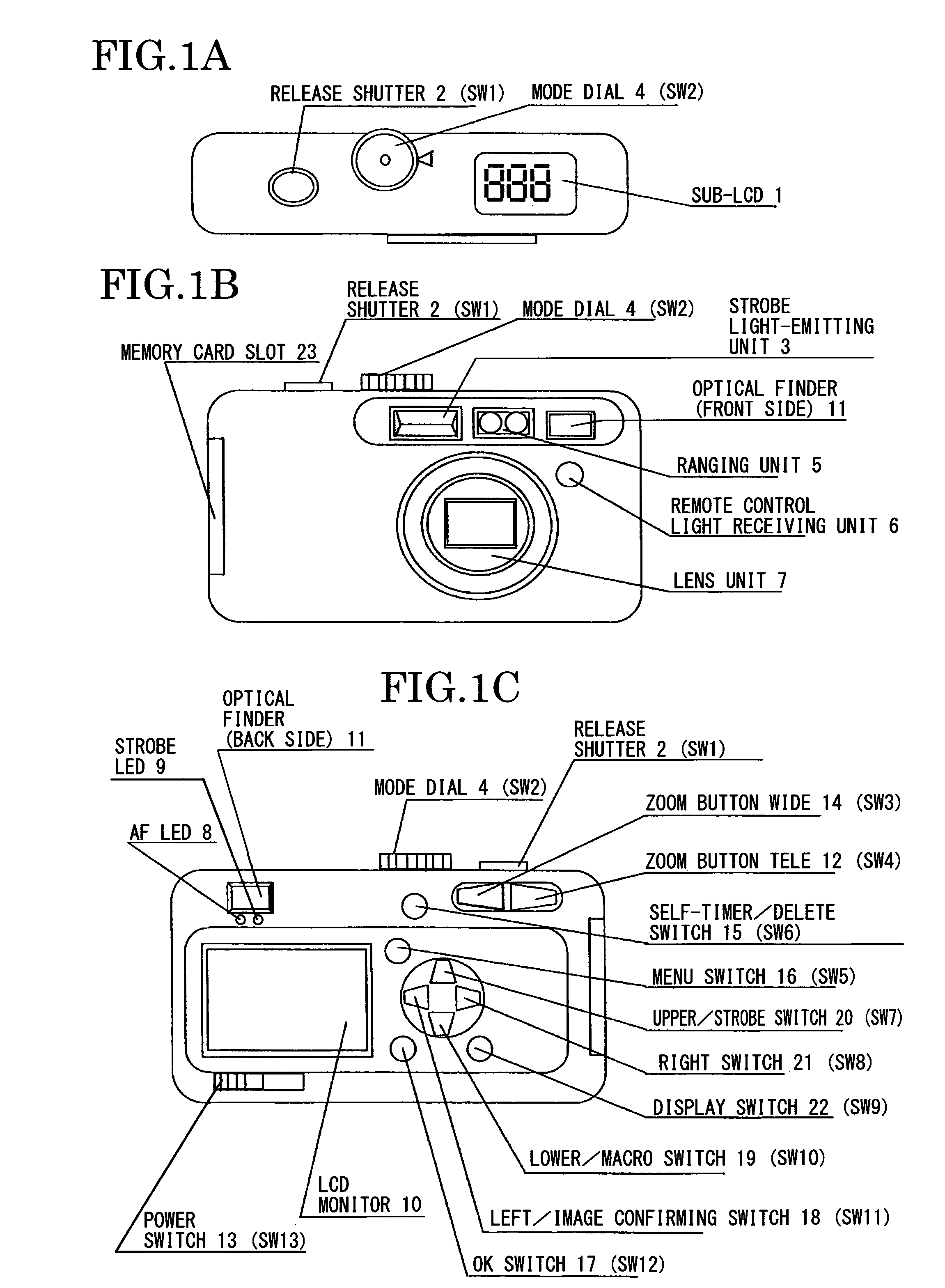
[0020]Hereinafter, a structure of an imaging apparatus according to an embodiment of the present invention will be explained in detail with reference to the accompanying drawings FIGS. 1A to 6.

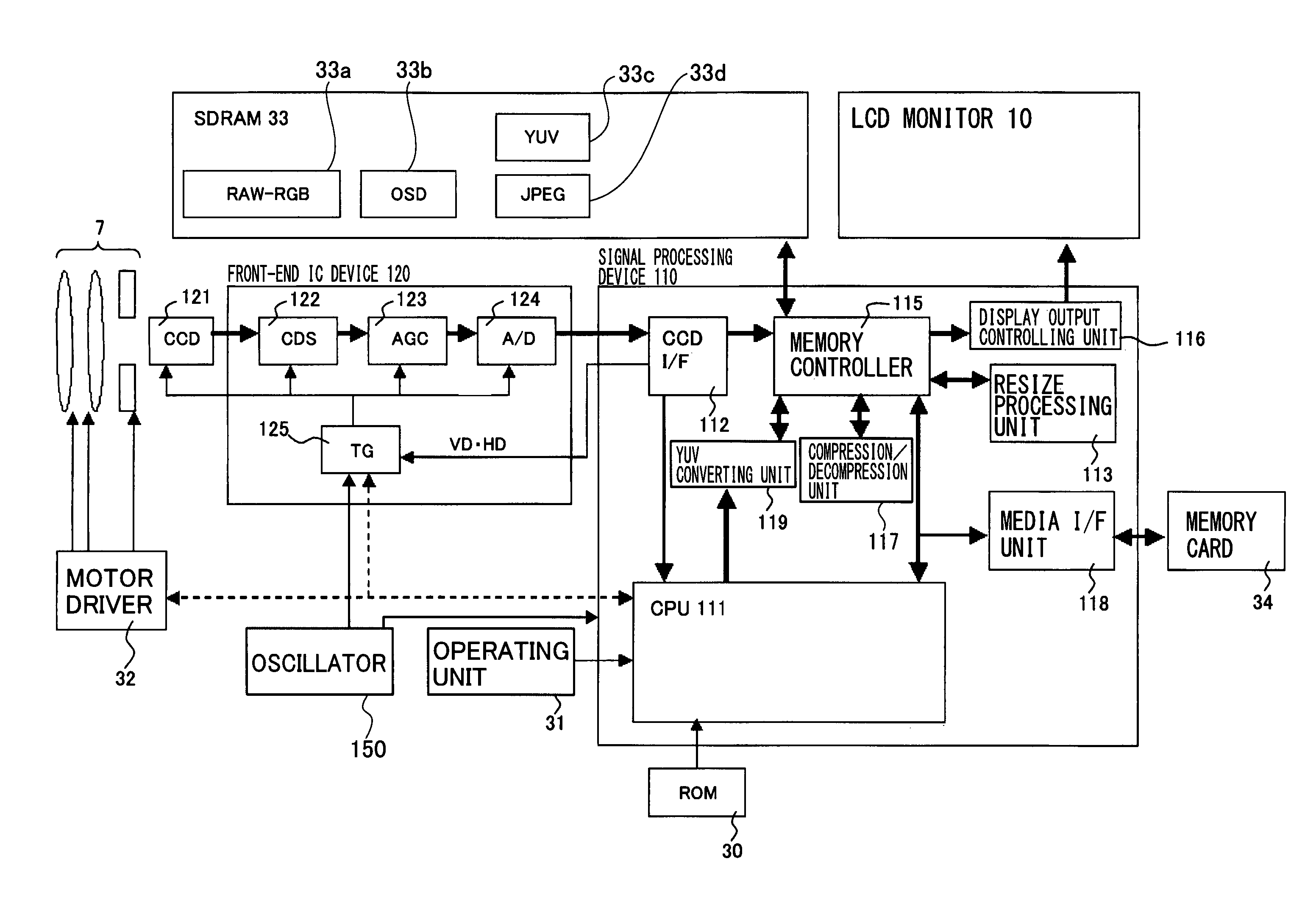
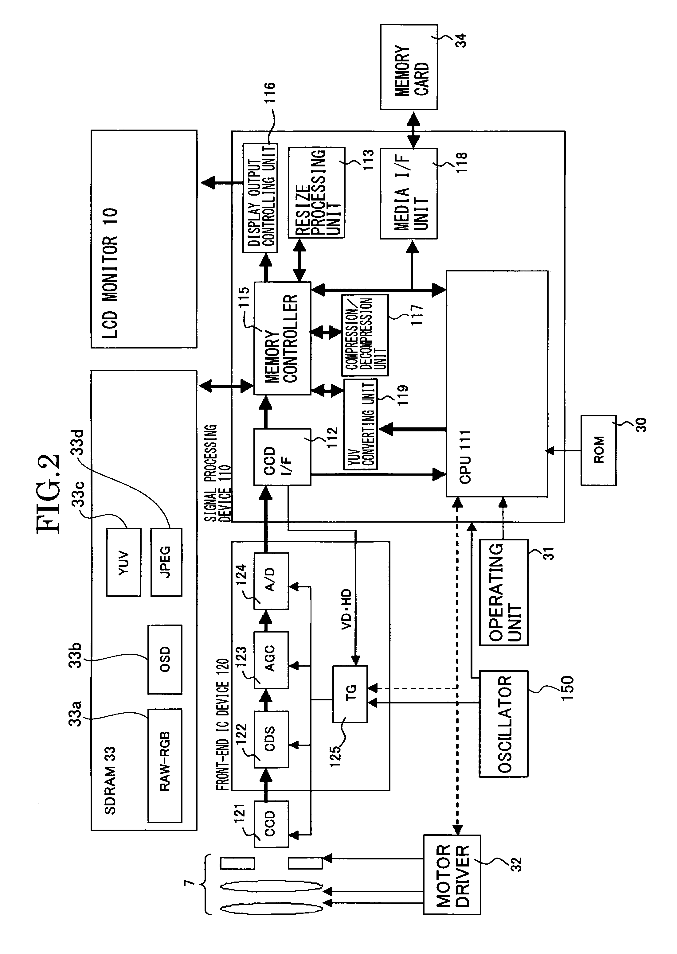
[0021]The imaging apparatus according to an embodiment of the present invention includes, for example, as shown in FIG.2, an image pickup device 121 configured to output an image signal, an analog image processing device 120, for example a front-end IC device 120 connected to the image pickup device 121, a digital image processing device 110, for example a signal processing device 110 connected to the front-end IC device 120, a display unit 10 connected to the signal processing device 110, and an SDRAM (Synchronous Dynamic Random Access Memory) 33 connected to the signal processing device 110.

[0022]The front-end IC device 120 includes a CDS (Correlated Double Sampling) 122 connected to the image pickup device 121, an AGC (Auto Gain Control) 123 connected to the CDS 122, an A / D converter 124 co...


PUM


Abstract

An imaging apparatus includes an image pickup device configured to output an image signal, an analog image processing device having an A / D converter configured to convert the output image signal from the image pickup device into a digital image signal and transfer the digital image signal, a digital image processing device configured to load the transferred digital image signal and perform an image processing on the loaded digital image signal, a clock generator configured to supply a clock having a frequency to each of the image pickup device, the analog image processing device, and the digital image processing device to drive the image pickup device, the analog image processing device and the digital image processing device at a predetermined driving frequency, and a controller configured to perform a monitoring stop processing to stop the transfer of the digital image signal from the analog image processing device and the image processing of the digital image processing device in a predetermined state.

Description

TECHNICAL FIELD[0001]The present invention relates to an imaging apparatus and an imaging method, more specifically, to an imaging apparatus and an imaging method suitable to reduce a release time lag in photographing.BACKGROUND ART[0002]As to imaging apparatuses such as digital still cameras (hereinafter, referred to as digital cameras), it is important to increase the battery life. Consequently, methods to achieve power saving in the control of a digital camera are conventionally used. As one of them, there is a technology to try power saving by lowering a frame rate during monitoring.[0003]The frame rate can be lowered by lowering a frequency of a clock to be supplied to an image pickup device, a timing generator (hereinafter, referred to as TG), an A / D converter, and the like. Since a rate of output of data from an image sensor is lowered by lowering the frame rate, power consumption per unit time in a signal processing IC can be reduced.[0004]As such a technology, for example, ...

Claims


Application Information

Patent Timeline
Patent Type & Authority Patents(United States)
IPC IPC(8): H04N5/228
CPCH04N5/232H04N5/23241H04N5/23245H04N5/343H04N2101/00H04N23/673H04N23/651H04N23/667H04N23/63H04N25/42
Inventor SUITO, HIROSHI
Owner RICOH KK
Learn More