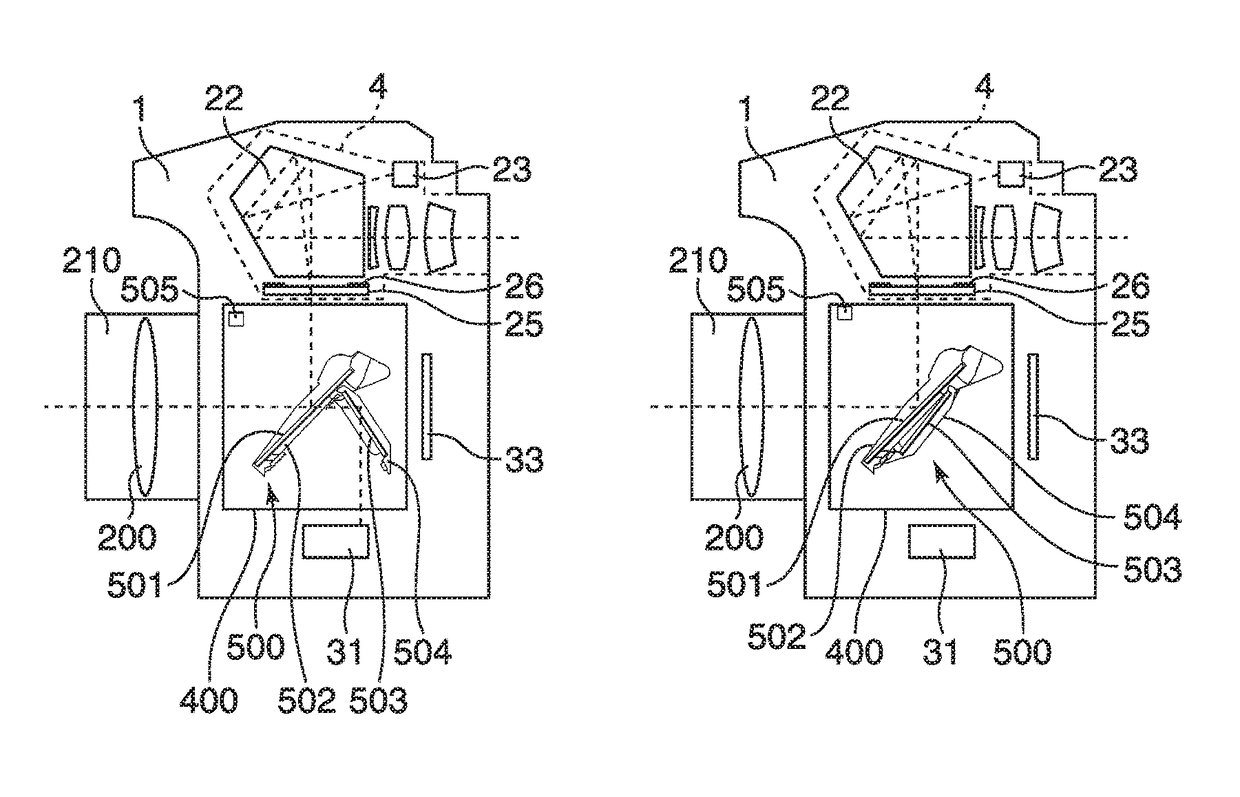
Image pickup apparatus including mirror unit and method of controlling the same
a pickup apparatus and image technology, applied in the direction of focusing aids, instruments, television systems, etc., can solve the problems of increasing the light amount, reducing the light guided to the viewfinder optical system, and increasing the dark finder image, so as to reduce the release time lag
- Summary
- Abstract
- Description
- Claims
- Application Information
AI Technical Summary
Benefits of technology
Problems solved by technology
Method used
Image
Examples
first embodiment
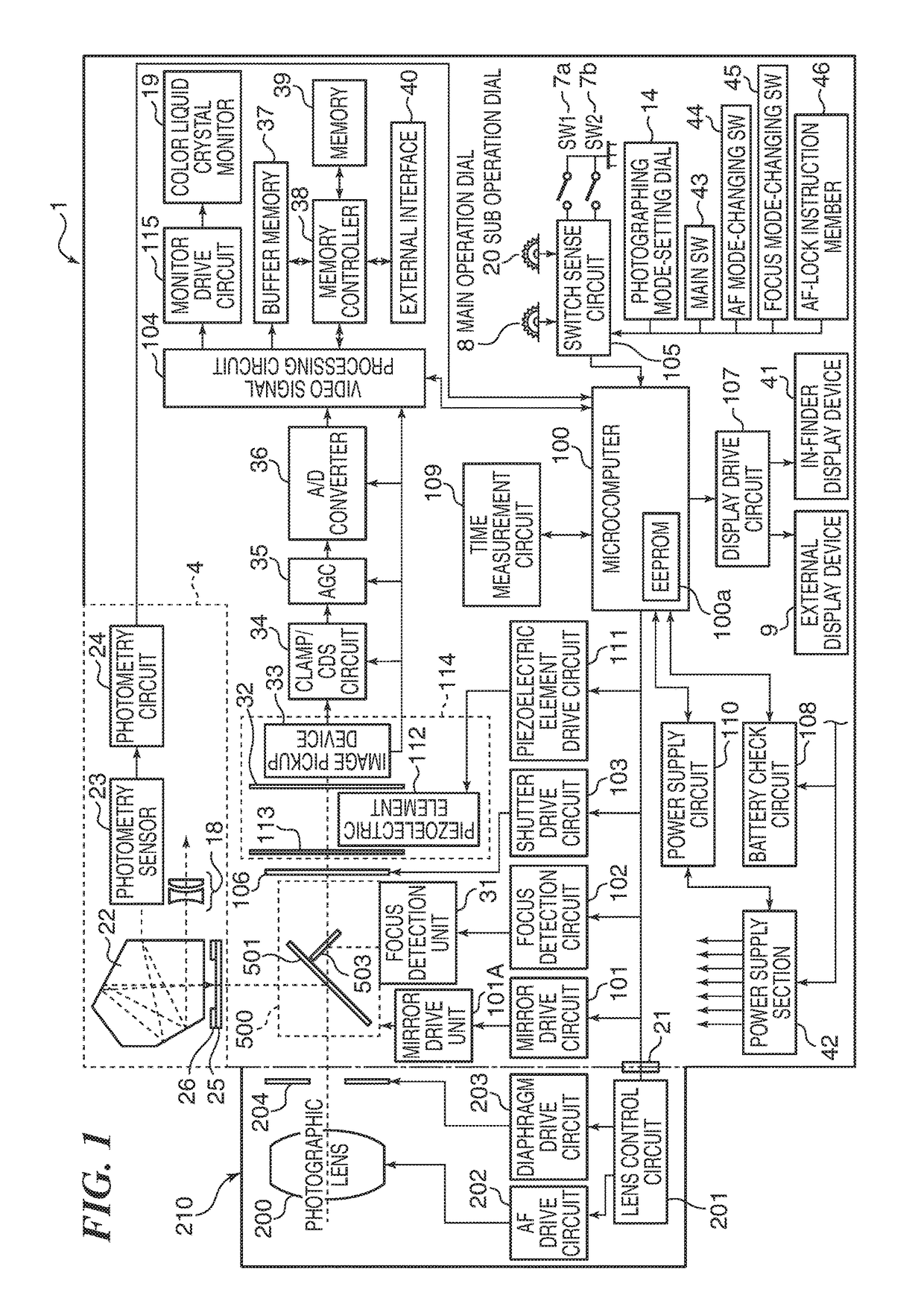
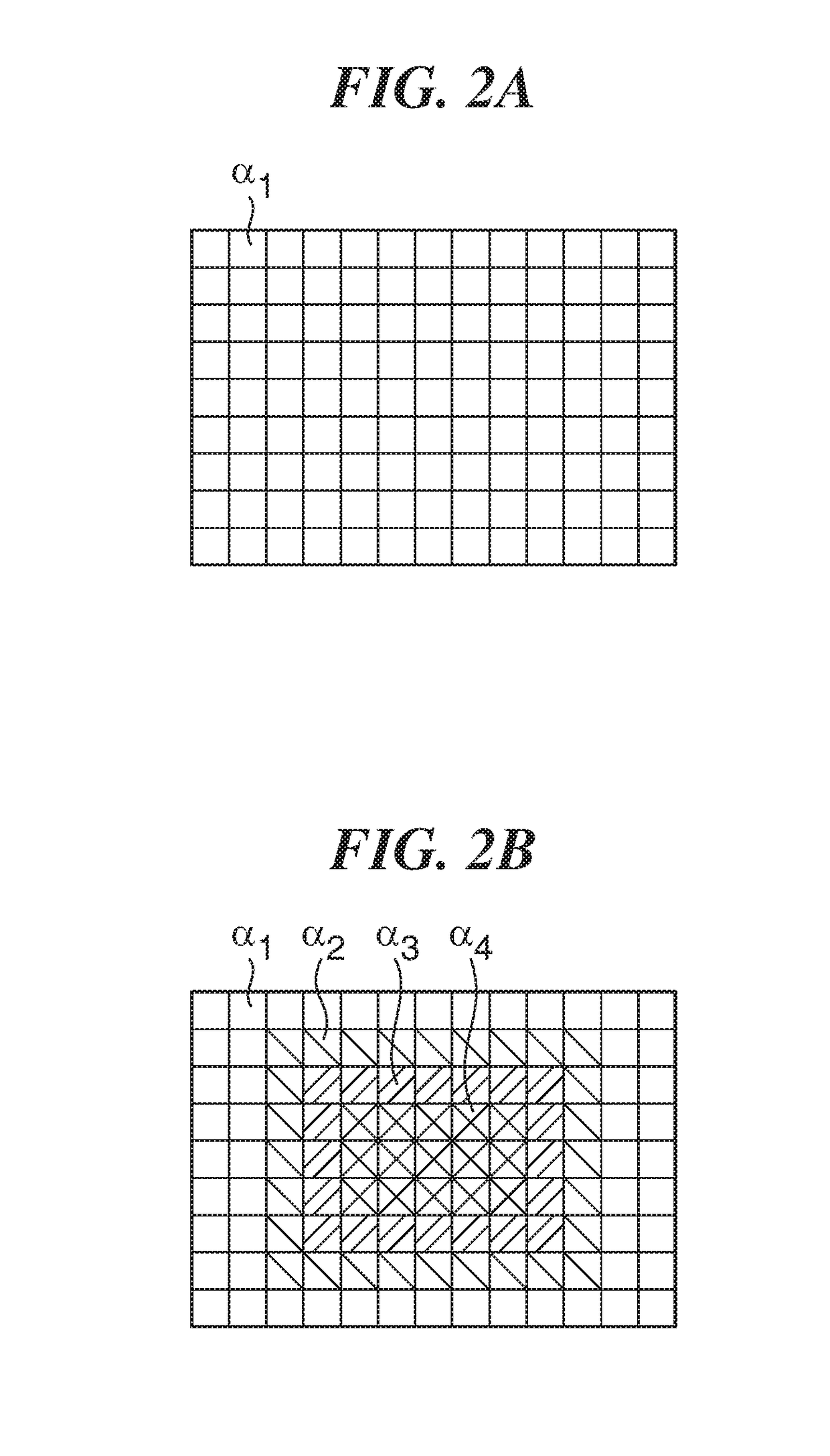
[0043]FIG. 1 is a system block diagram of a digital single-lens reflex camera as an image pickup apparatus according to the present invention. FIGS. 2A and 2B are output correction charts used when correcting an output value from a photometry sensor.
[0044]As shown in FIG. 1, in the digital single-lens reflex camera (hereinafter referred to as the camera) as an image pickup apparatus according to the present embodiment, an interchangeable lens unit 210 is mounted on a camera body 1 via a mount contact portion 21 in a removable manner.
[0045]First, a description will be given of the camera body 1. In FIG. 1, a microcomputer 100 (hereinafter referred to as the MPU 100) controls the overall operation of the camera. An EEPROM 100a incorporated in the MPU 100 stores time information of a time measurement circuit 109, programs, and other information items. To the MPU 100, there are connected a mirror drive circuit 101, a focus detection circuit 102, a shutter drive circuit 103, a video sign...
second embodiment
[0156]Referring to FIG. 17, in the second embodiment, the strobe drive circuit 600 is also connected to the MPU 100. The strobe drive circuit 600 is connected to the strobe unit 601 to drive the same.
[0157]The photometry sensor 23 detects part of a photographing light flux by the light receiving elements which are divided in association with the areas on the observation surface. The photometric circuit 24 converts output values from the photometry sensor 23 to luminance signals of the respective areas on the observation surface, and outputs the luminance signals to the MPU 100. The MPU 100 calculates an exposure value based on the luminance signals output from the photometric circuit 24. Further, when performing final strobe light emission, the MPU 100 calculates an amount of light necessary for the final strobe light emission based on the luminance signals output from the photometric circuit 24 during preliminary strobe light emission.
[0158]The strobe drive circuit 600 includes a c...
PUM
 Abstract
Description
Claims
Application Information
 - R&D
- Intellectual Property
- Life Sciences
- Materials
- Tech Scout
- Unparalleled Data Quality
- Higher Quality Content
- 60% Fewer Hallucinations
Browse by: Latest US Patents, China's latest patents, Technical Efficacy Thesaurus, Application Domain, Technology Topic, Popular Technical Reports.
© 2025 PatSnap. All rights reserved.Legal|Privacy policy|Modern Slavery Act Transparency Statement|Sitemap|About US| Contact US: help@patsnap.com


