Imaging apparatus and control method and program of imaging apparatus

a technology of imaging apparatus and control method, applied in the field of imaging apparatus, can solve problems such as release time lag, and achieve the effect of reducing the release time lag

Active Publication Date: 2016-02-02
CANON KK
View PDF9 Cites 0 Cited by
  • Summary
  • Abstract
  • Description
  • Claims
  • Application Information

AI Technical Summary

Benefits of technology

[0007]It is, therefore, an aspect of the invention to provide an imaging apparatus which can obtain image data which can be refocused to a user's desired object while reducing a release time lag.

Problems solved by technology

However, the imaging apparatus disclosed in Japanese Patent No. 4752031 has such a problem that there is a case where a range in which an image can be refocused by the user differs from a user's desired range.
The imaging apparatus disclosed in Japanese Patent Application Laid-Open No, 2010-213038 has such a problem that since defocus amounts are calculated with respect to a plurality of object area upon photographing and a release is performed, a release time lag occurs.

Method used


Image

  • Imaging apparatus and control method and program of imaging apparatus
  • Imaging apparatus and control method and program of imaging apparatus
  • Imaging apparatus and control method and program of imaging apparatus

Examples


first embodiment

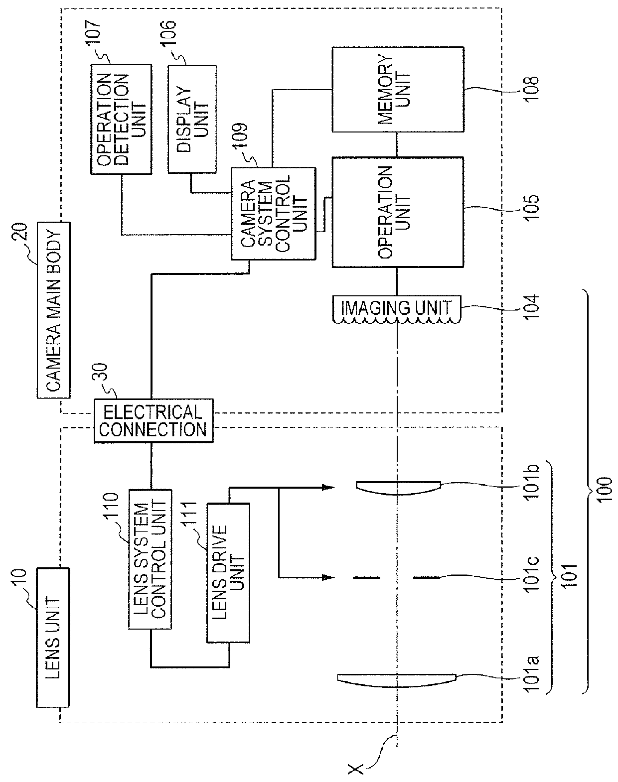
[0028]FIG. 1 is a diagram illustrating a construction of a main portion of an imaging apparatus according to the first embodiment of the invention.

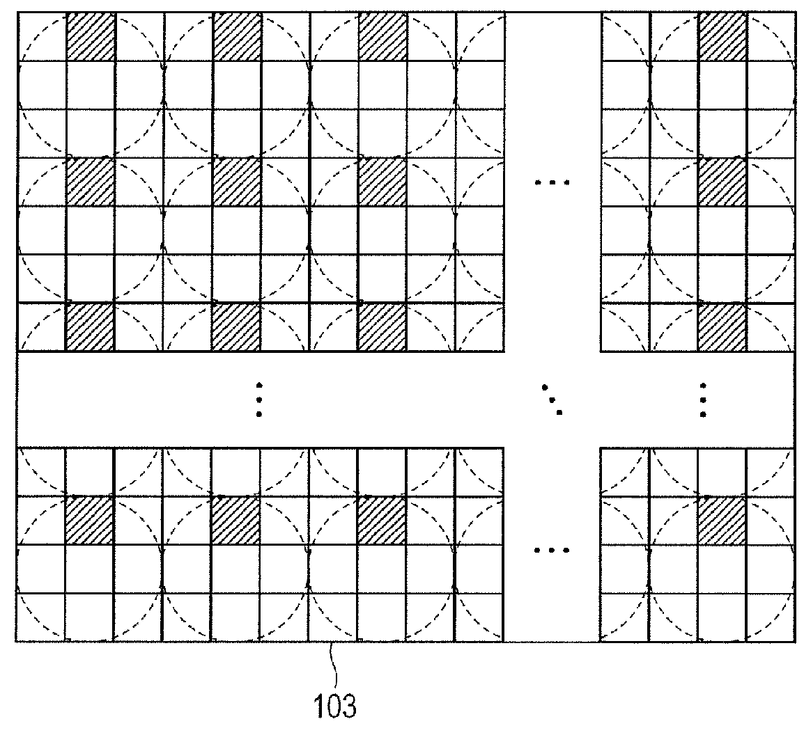
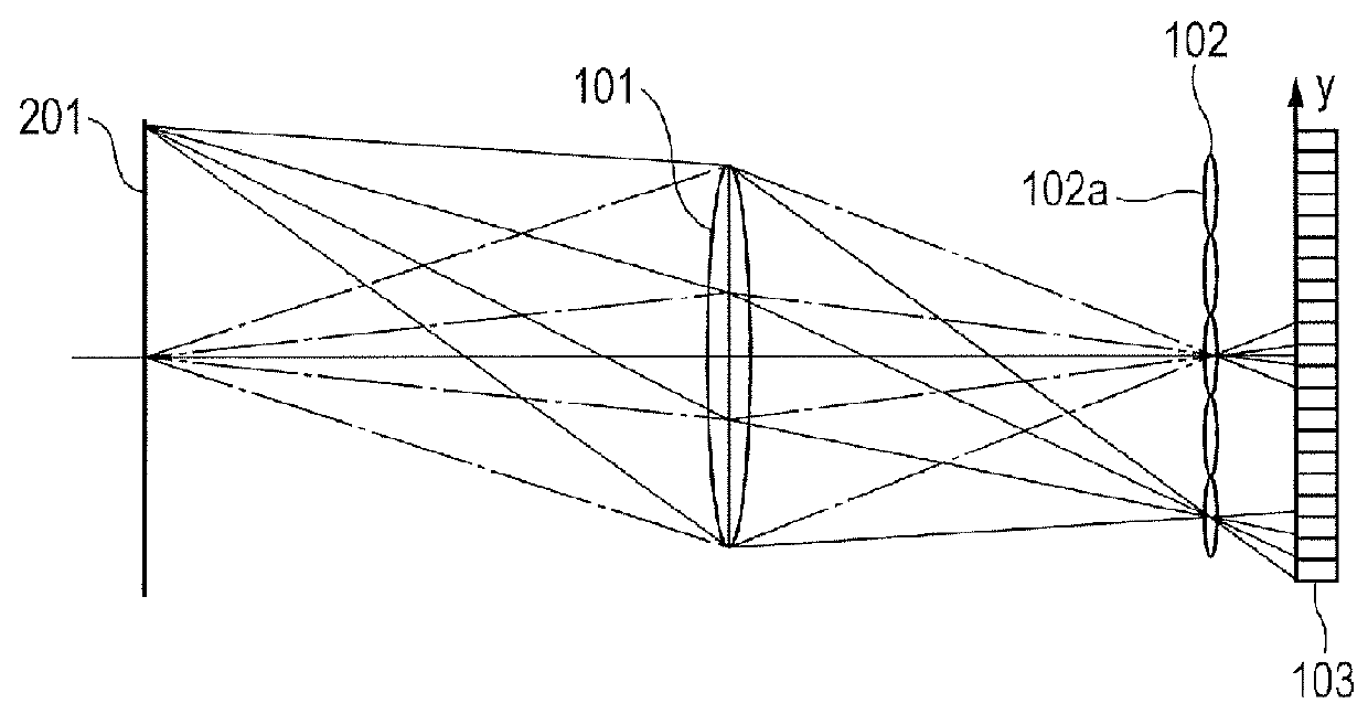
[0029]In the diagram, a lens unit 10 of an interchangeable lens type and a camera main body 20 are connected through an electrical connection 30. An image formation optical system 101 forms an optical image of an object. The image formation optical system 101 is constructed by: a zoom lens group 101a constructed by a plurality of lenses for performing a magnification operation of the optical image; a focus lens group 101b constructed by a plurality of lenses for performing a focus adjustment; and an iris 101c. Each of the zoom lens group 101a and the focus lens group 101b is illustrated as a single lens for simplicity of explanation. An imaging unit 104 is constructed by a microlens array (hereinbelow, referred to as “MLA”) 102; and a two-dimensional imaging element 103 having a photoelectric conversion unit such as CCD, CMOS, or the like...

second embodiment

[0079]Subsequently, the second embodiment of the imaging apparatus to which the invention is applied will be described. Since a construction of a main portion of the imaging apparatus according to the present embodiment is similar to that in the first embodiment, its description is omitted here. It is assumed that a photographed scene is similar to that in the first embodiment.

[0080]Although the optimum position of the focus lens upon photographing is predicted in the first embodiment, a range of the refocus-possible lens position is predicted and the lens optimum position is determined from the predicted range in the second embodiment. Thus, after the release button is depressed, the arithmetic operation of the object distance or the like becomes unnecessary similarly to the first embodiment.

[0081]FIGS. 11A and 11B are diagrams illustrating a flowchart for the photographing operation of the imaging apparatus according to the present embodiment. Since the operations in steps S901 to...

third embodiment

[0090]Subsequently, the third embodiment of the invention will be described. Since a construction of a main portion of the imaging apparatus according to the present embodiment is similar to that in the first embodiment, its description is omitted here.

[0091]FIG. 13 is a diagram illustrating a photographed scene in the present embodiment. In the diagram, although a positional relation between the distant position and near position of objects in the image angle is substantially the same as the positional relation illustrated in FIG. 5, each object moves as follows. The objects A and B are moving in the coming-up direction toward the imaging apparatus. The object C is moving in the leaving direction from the imaging apparatus. That is, since all of the objects are moving in the present embodiment, the present embodiment is effective to the photographing of scenes in various situations as compared with the first or second embodiment showing a case where only the object nearest to the i...


PUM


Abstract

An imaging apparatus having an image formation optical system having a lens for focus adjustment of an optical image of an object and an imaging unit for picking up the formed optical image and generating a pixel signal from which a refocus image can be generated includes: a calculation unit for obtaining information of the object the optical image of which is picked up by the imaging unit and calculating, based on the obtained object information, a range of a lens position at which the refocus image of the object being in-focus can be generated; a prediction unit for predicting, based on the lens position range, a change of the calculated lens position at which the refocus image of the object being in-focus can be generated; and a determination unit for determining a drive position of the lens based on a prediction result.

Description

BACKGROUND OF THE INVENTION[0001]1. Field of the Invention[0002]The present invention relates to an imaging apparatus and, more particularly, to an imaging apparatus which can generate image data which can be refocused and a control method of such an imaging apparatus.[0003]2. Description of the Related Art[0004]In recent years, an imaging apparatus which outputs various kinds of images by executing an arithmetic operation to data obtained by an imaging element and executing a digital image processing corresponding to the arithmetic operation is proposed. Japanese Patent No. 4752031 discloses an imaging apparatus which simultaneously obtains two-dimensional intensity distribution of light of an object space and angular information of a ray of light, that is, parallax information by using “Light Field Photography”. The two-dimensional intensity distribution of light and the angular information of the ray of light are together called “light field”. By obtaining the light field, three-...

Claims


Application Information

Patent Timeline
Patent Type & Authority Patents(United States)
IPC IPC(8): H04N5/232G02B7/34G03B35/12
CPCH04N5/23212G02B7/34H04N5/23229G03B35/12H04N23/67H04N23/80
Inventor HASHIMOTO, YOSHITAKAYAMAMOTO, YASUFUMI
Owner CANON KK
Why Eureka
Try Eureka