
Image pickup apparatus including mirror unit and method of controlling the same

Inactive Publication Date: 2017-07-06
CANON KK
View PDF7 Cites 0 Cited by
  • Summary
  • Abstract
  • Description
  • Claims
  • Application Information

AI Technical Summary

Benefits of technology

The present invention is an image pickup apparatus that reduces the time it takes to release the shutter. This is achieved by controlling the operation of a mirror holder in a mirror-up operation. The invention also reduces the release time lag without affecting the photometric value, by rotating the mirror holder to a position and holding it in advance. Additionally, it improves object visibility and the accuracy of photometry in low luminance environments by increasing the amount of light guided to the viewfinder optical system. The invention also enables the image pickup apparatus to obtain an accurate amount of final strobe light emission without increasing the amount of electric power necessary for preliminary strobe light emission.

Problems solved by technology

On the other hand, the technique disclosed in Japanese Patent Laid-Open Publication No. 2001-83402 has a problem that when a sufficient amount of light is to be guided to the focus detection optical system, the amount of light guided to the viewfinder optical system is reduced, which brings about a problem of a dark finder image.
Therefore, in the technique disclosed in Japanese Patent Laid-Open Publication No. 2007-322895, to obtain an accurate amount of final strobe light emission for a photographic scene which is dark with a large camera-to-object distance, or the like, it is necessary to increase the light amount of preliminary strobe light emission, which increases power consumption.

Method used


Image

  • Image pickup apparatus including mirror unit and method of controlling the same
  • Image pickup apparatus including mirror unit and method of controlling the same
  • Image pickup apparatus including mirror unit and method of controlling the same

Examples


first embodiment

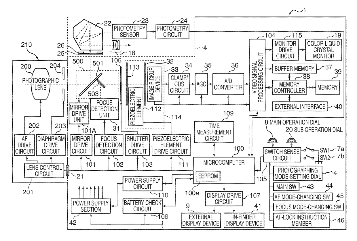
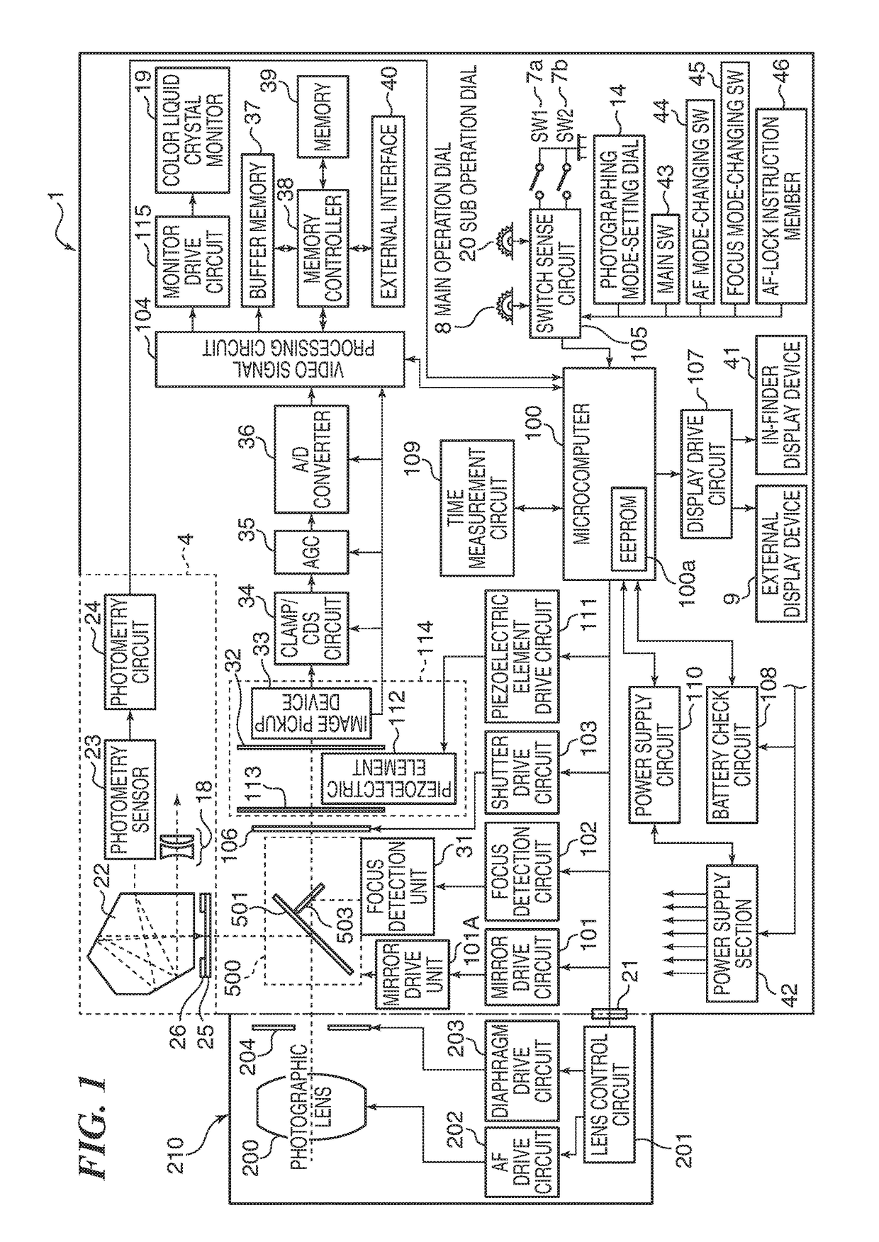
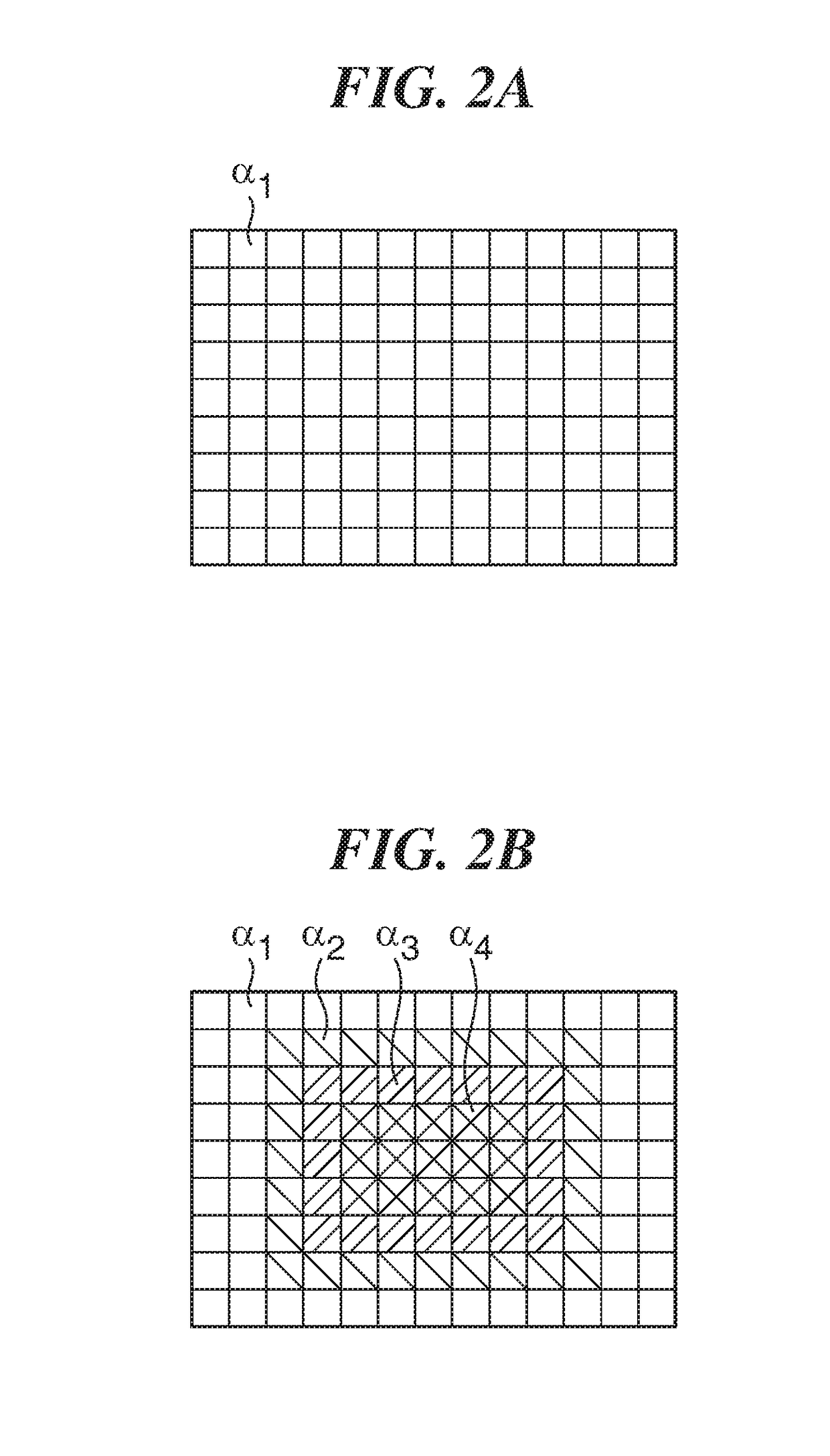
[0043]FIG. 1 is a system block diagram of a digital single-lens reflex camera as an image pickup apparatus according to the present invention. FIGS. 2A and 2B are output correction charts used when correcting an output value from a photometry sensor.

[0044]As shown in FIG. 1, in the digital single-lens reflex camera (hereinafter referred to as the camera) as an image pickup apparatus according to the present embodiment, an interchangeable lens unit 210 is mounted on a camera body 1 via a mount contact portion 21 in a removable manner.

[0045]First, a description will be given of the camera body 1. In FIG. 1, a microcomputer 100 (hereinafter referred to as the MPU 100) controls the overall operation of the camera. An EEPROM 100a incorporated in the MPU 100 stores time information of a time measurement circuit 109, programs, and other information items. To the MPU 100, there are connected a mirror drive circuit 101, a focus detection circuit 102, a shutter drive circuit 103, a video sign...

second embodiment

[0156]Referring to FIG. 17, in the second embodiment, the strobe drive circuit 600 is also connected to the MPU 100. The strobe drive circuit 600 is connected to the strobe unit 601 to drive the same.

[0157]The photometry sensor 23 detects part of a photographing light flux by the light receiving elements which are divided in association with the areas on the observation surface. The photometric circuit 24 converts output values from the photometry sensor 23 to luminance signals of the respective areas on the observation surface, and outputs the luminance signals to the MPU 100. The MPU 100 calculates an exposure value based on the luminance signals output from the photometric circuit 24. Further, when performing final strobe light emission, the MPU 100 calculates an amount of light necessary for the final strobe light emission based on the luminance signals output from the photometric circuit 24 during preliminary strobe light emission.

[0158]The strobe drive circuit 600 includes a c...


PUM


Abstract

An image pickup apparatus enabling release time lag reduction. A first holder holds a first mirror and is movable between a first position in an optical path and a second position retracted from the optical path. A second holder holding a second mirror in a state rotatably attached to the first holder is movable between a third position in the optical path and a fourth position retracted from the optical path. An MPU causes an mirror drive unit to rotate the second holder in the third position toward the first holder in the first position, after termination of focus detection when the first and second holder are in the first and third positions, respectively, and before image pickup is instructed, to thereby move the second holder to a fifth position closer to the first holder than the third position is.

Description

BACKGROUND OF THE INVENTION[0001]Field of the Invention[0002]The present invention relates to an image pickup apparatus, such as a single-lens reflex camera, and more particularly to a technique for controlling the operation and driving of a quick return mirror, such as correction control of an output value from a photometric unit in driving the quick return mirror, and a technique for controlling the operation of the quick return mirror in strobe photographing.[0003]Description of the Related Art[0004]An image pickup apparatus, such as a single-lens reflex camera, is provided with a quick return mirror mechanism including a main mirror holder for holding a main mirror formed by a half mirror, and a sub mirror holder that holds a sub mirror and is rotatably supported with respect to the main mirror holder. The quick return mirror mechanism enters a photographing optical path (mirror down) to guide an object light flux having passed through a photographing optical system to a viewfin...

Claims


Application Information

Patent Timeline
IPC IPC(8): H04N5/232G03B19/12G02B26/08H04N5/225
CPCH04N5/23212H04N5/23293G02B26/0816H04N5/2256G03B19/12H04N5/2254G03B13/36H04N23/56H04N23/663H04N23/667H04N23/71H04N23/74
Inventor TAMURA, KOJIKAMIYA, JUNIWASAKI, SHOGOUEDA, HARUHISAYAMANA, KAZUAKIMORITA, KEISUKE
Owner CANON KK
Learn More