Apparatus and method to machine holes

a technology of machining equipment and machining method, which is applied in the direction of manufacturing tools, laser beam welding apparatus, welding apparatus, etc., can solve the problems of one machine saving significant costs on the one hand for machining equipment and on the other hand for machining itsel

Inactive Publication Date: 2013-12-31
SIEMENS AG
View PDF16 Cites 3 Cited by
  • Summary
  • Abstract
  • Description
  • Claims
  • Application Information

AI Technical Summary

Benefits of technology

[0005]Therefore it is one object of the invention to design an apparatus and a method for machining holes in the above mentioned manner, which guarantees a high degree of accuracy, enables the necessary flexibility in geometry of the holes but simplifies the machining significantly.
[0006]It is a further object to reduce the manufacturing costs, especially to reduce the processing time for gas turbine blades and the costs for the machining apparatus.

Problems solved by technology

Enabling both manufacturing methods with one machine saves significant costs on the one hand for machining equipment and on the other hand for the machining itself since separate alignments for different machining procedures are not necessary.

Method used


Image

  • Apparatus and method to machine holes
  • Apparatus and method to machine holes

Examples


Embodiment Construction

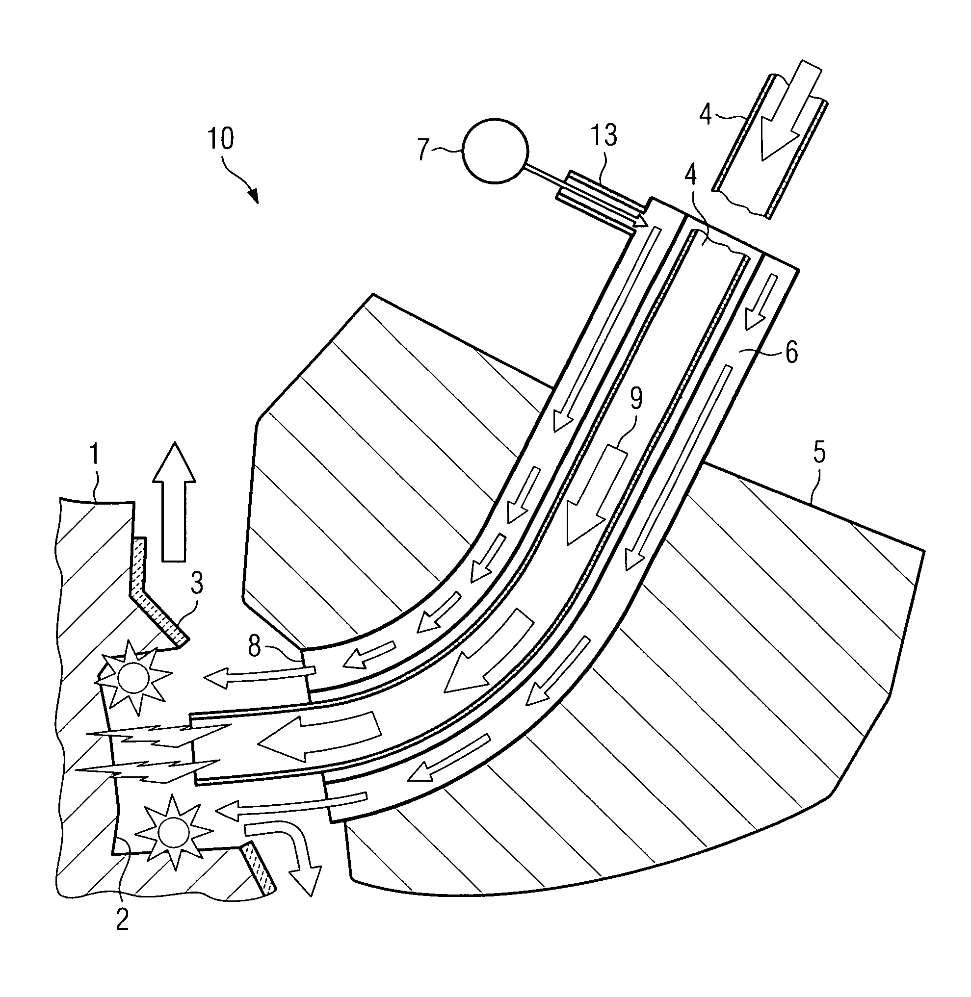
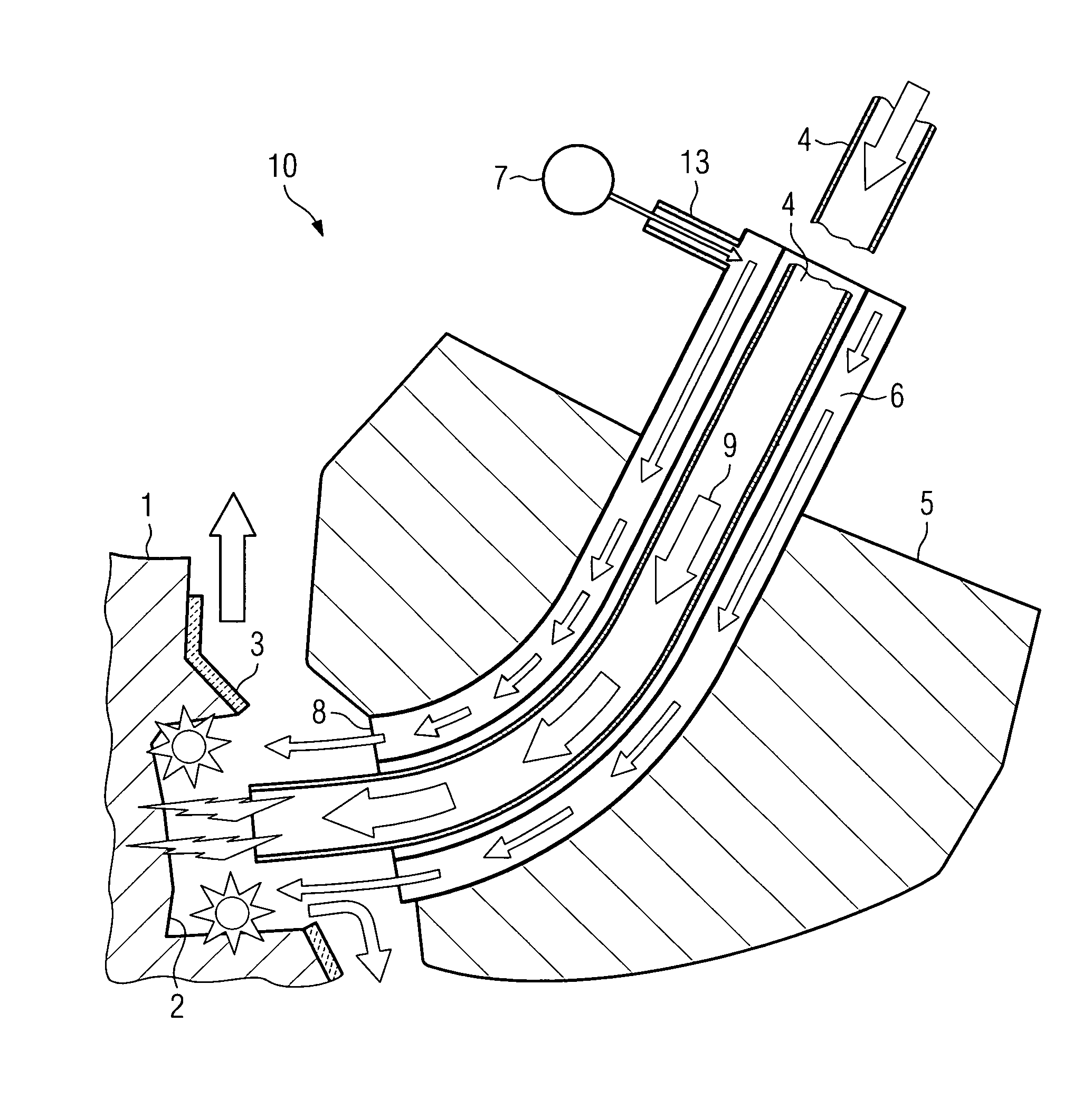
[0026]FIG. 1 shows the main components of an apparatus 10 to machine a hole into a surface 1 according to the invention. The surface 1 is part of a non-further depicted gas turbine blade airfoil with a ceramic coating layer 3 on the surface 1. In a first step of the method according to the invention laser light from a laser 7 enters a light conductive tube 6 through an optical adapter 13. The optical adapter 13 distributes the laser light harmonically over the whole circumference of the light conductive tube 6. The laser light leaves the light conductive tube 6 at an emission module 8 respectively emission surface of the light conductive tube 6. The emission module 8 is directed to an area of the surface 1, where a ceramic coating 3 is removed.

[0027]An electrode 4 of diameter dy1 of tubular shape is led through the inner diameter of the light conductive tube 6. During the first step this electrode 4 is retracted. After finishing of the first step respectively the removal of the coat...


PUM

PropertyMeasurementUnit
inner diameteraaaaaaaaaa

Abstract

The present invention relates to an apparatus for machining holes, especially to machine holes in a surface of a coated gas turbine airfoil, which apparatus comprises a laser device for laser drilling and an electrode for electrical discharge machining. Further the invention relates to a method to machine a hole into a coated surface with an apparatus of the incipiently mentioned type. Known methods make use of a machine with separate machine heads for laser drilling and electrical discharge machining. By combining these two devices in one machine head the invention gives the possibility to save time and obtain very accurate results.

Description

CROSS REFERENCE TO RELATED APPLICATIONS[0001]This application claims the benefits of European application No. 07022765.7 filed Nov. 23, 2007 and is incorporated by reference herein in its entirety.FIELD OF INVENTION[0002]The present invention relates to an apparatus for machining holes, especially to machine holes in a surface of a coated gas turbine airfoil, which apparatus comprises a laser device for laser drilling and an electrode for electrical discharge machining, wherein the laser device comprises an emission module with an emission surface to emit the laser beam directed in a defined direction. Further the invention relates to a method to machine a hole into a coated surface with an apparatus of the incipiently mentioned type.BACKGROUND OF THE INVENTION[0003]Machining holes into turbine blades, in particular into cooled gas turbine blades is an extraordinary difficult tasks, since the airfoils of the blades have convex and concave three dimensional surfaces and the optimal t...

Claims


Application Information

Patent Timeline
Patent Type & Authority Patents(United States)
IPC IPC(8): B23K26/00B23K9/00
CPCB23H9/00B23H5/04B23H9/14B23H9/10
Inventor GRAICHEN, ANDREAS
Owner SIEMENS AG
Why Eureka
Try Eureka