Expandable intraluminal graft

a technology expanding graft, which is applied in the field of expanding intraluminal graft, can solve the problems of inability to change the expansion size of the graft, no effective control over the final, and the foregoing structure has one major disadvantage in common, so as to prevent recurrence of stenoses and prevent erosion of the body passageway

Inactive Publication Date: 2006-07-06
SCHATZ RICHARD A +1
View PDF77 Cites 2 Cited by
  • Summary
  • Abstract
  • Description
  • Claims
  • Application Information

AI Technical Summary

Benefits of technology

[0013] The expandable intraluminal vascular graft of the present invention, when compared with previously proposed prior art intraluminal grafts, has the advantages of: preventing recurrence of stenoses; is believed to permit implantation of grafts in critical body passageways, such as in the left main coronary artery of the heart; prevents recoil of the body passageway; prevents erosion of the body passageway by the expanded graft; permits expansion of the graft to a variable size dependent upon conditions within the body passageway; permits tissue of an elongated section of a body passageway to be supported by an elongated graft; and provides the necessary flexibility to negotiate the bends and curves in tortuous body passageways, such as the vascular system.

Problems solved by technology

In general, the foregoing structures have one major disadvantage in common.
Insofar as these structures must be delivered to the desired location within a given body passageway in a collapsed state, in order to pass through the body passageway, there is no effective control over the final, expanded configuration of each structure.
Thus, once the foregoing types of intraluminal grafts are expanded at the desired location within a body passageway, such as within an artery or vein, the expanded size of the graft cannot be changed.
Likewise, an oversized graft might expand to such an extent that the spring force, or expansion force, exerted by the graft upon the body passageway could cause rupturing of the body passageway.
Further, the constant outwardly radiating force exerted upon the interior surface of the body passageway can cause erosion of the internal surface, or intima, of the artery or body passageway.
Although the balloon dilation procedure is typically conducted in the catheterization lab of a hospital, because of the foregoing problem, it is always necessary to have a surgeon on call should the intimal flap block the blood vessel or body passageway.
Further, because of the possibility of the intimal flap tearing away from the blood vessel and blocking the lumen, balloon dilations cannot be performed upon certain critical body passageways, such as the left main coronary artery, which leads into the heart.
Additional disadvantages associated with balloon dilation of elastic vascular stenoses is that many fail because of elastic recoil of the stenotic lesion.
Thus, although the body passageway may initially be successfully expanded by a balloon dilation procedure, subsequent, early restenosis can occur due to the recoil of the body passageway wall which decreases the size of the previously expanded lumen of the body passageway.
Vascular stenoses caused by neointimal fibrosis, such as those seen in dialysis-access fistulas, have proved to be difficult to dilate, requiring high dilating pressures and larger balloon diameters.
Similar difficulties have been observed in angioplasties of graft-artery anastomotic strictures and postendarterectomy recurrent stenoses.
Percutaneous angioplasty of Takayasu arteritis and neurofibromatosis arterial stenoses may show poor initial response and recurrence which is believed due to the fibrotic nature of these lesions.
For repairing blood vessels narrowed or occluded by disease, or repairing other body passageways, the length of the body passageway which requires repair, as by the insertion of a tubular prosthetic graft, may present problems if the length of the required graft cannot negotiate the curves or bends of the body passageway through which the graft is passed by the catheter.

Method used


Image

  • Expandable intraluminal graft
  • Expandable intraluminal graft
  • Expandable intraluminal graft

Examples


Embodiment Construction

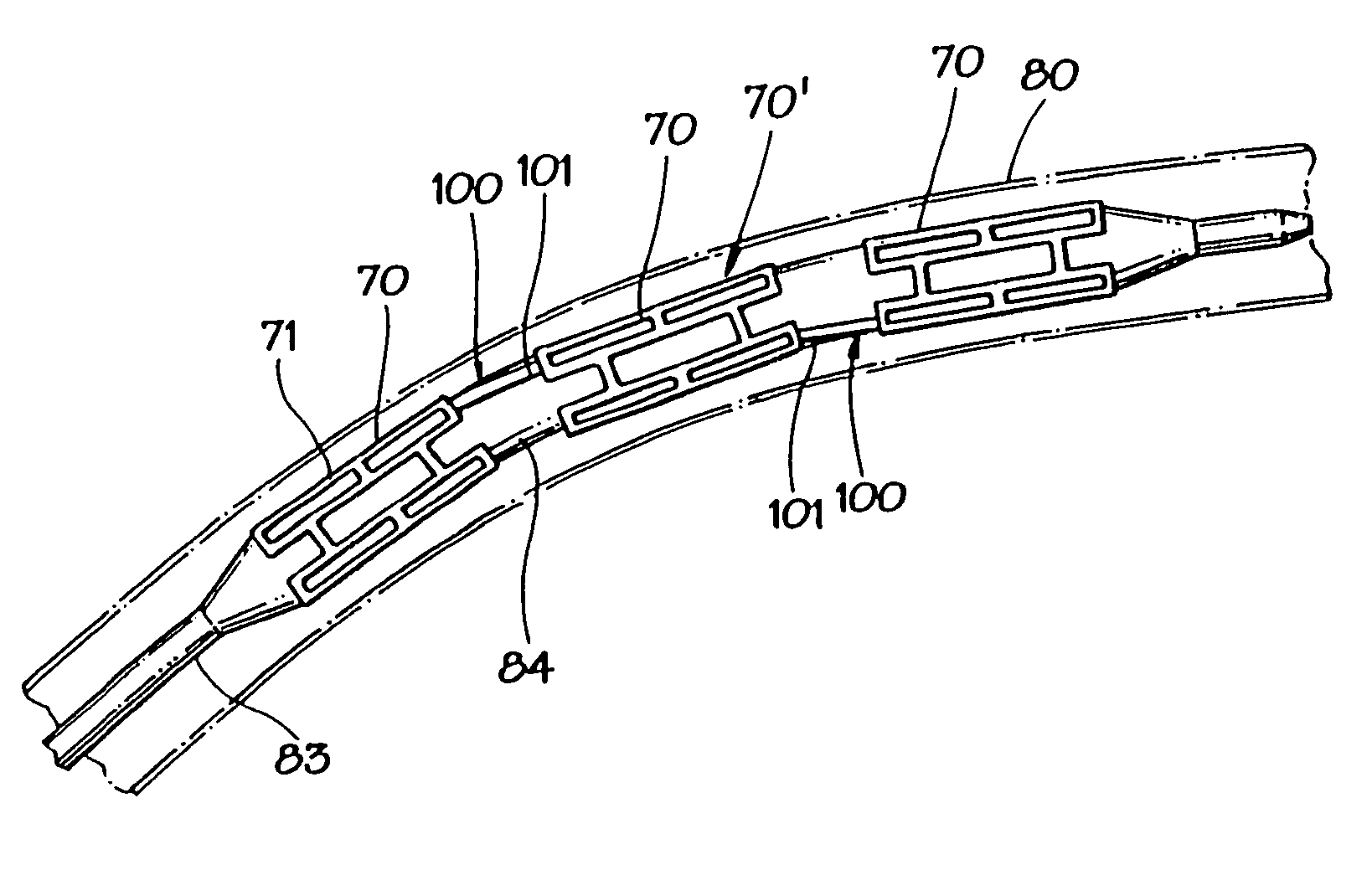
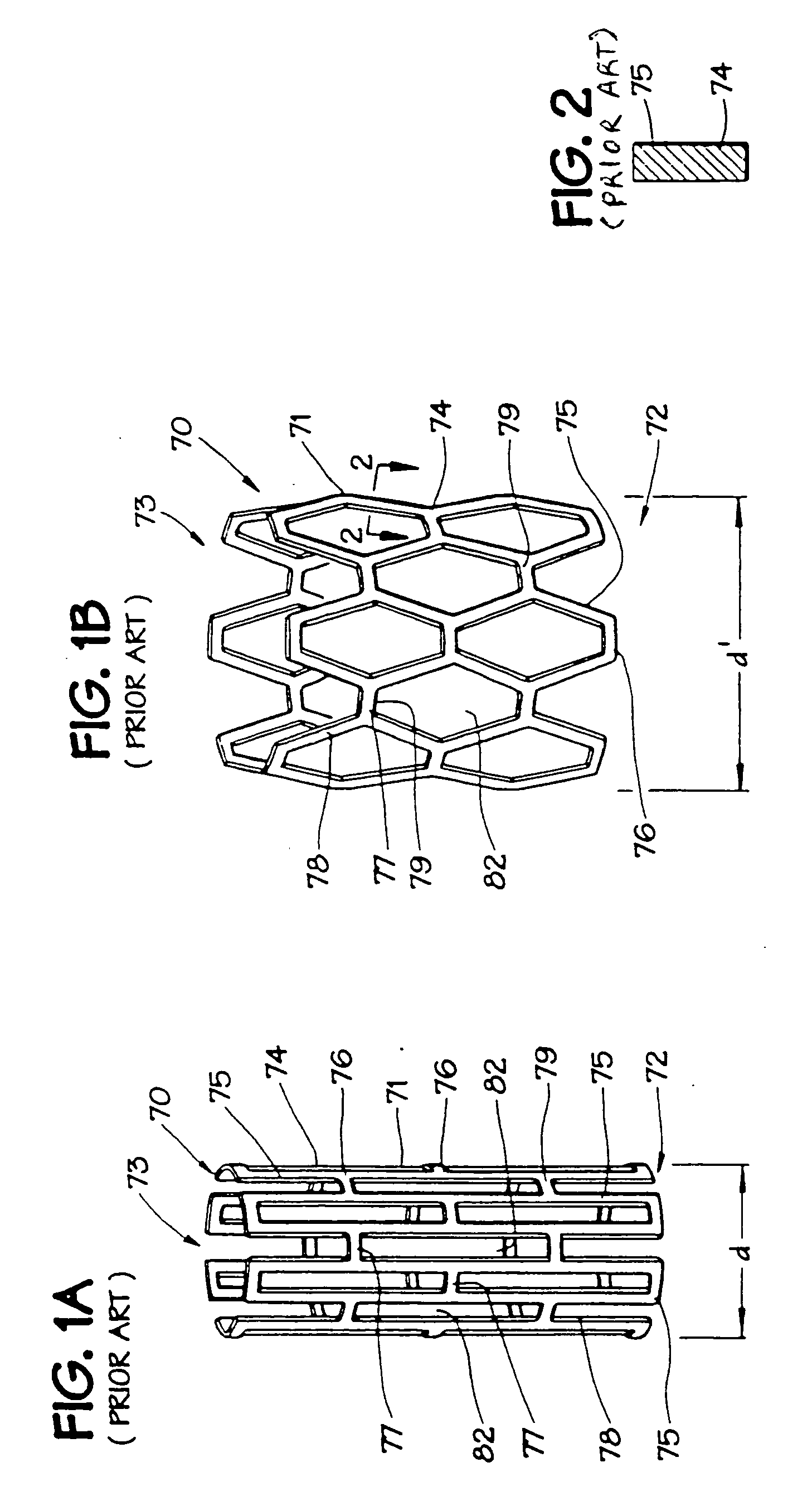
[0024] In FIGS. 1A and 1B, an expandable intraluminal vascular graft, or expandable prosthesis for a body passageway, 70 is illustrated. It should be understood that the terms “expandable intraluminal vascular graft” and “expandable prosthesis” are interchangeably used to some extent in describing the present invention, insofar as the methods, apparatus, and structures of the present invention may be utilized not only in connection with an expandable intraluminal vascular graft for expanding partially occluded segments of a blood vessel, or body passageway, but may also be utilized for many other purposes as an expandable prosthesis for many other types of body passageways. For example, expandable prostheses 70 may also be used for such purposes as: (1) supportive graft placement within blocked arteries opened by transluminal recanalization, but which are likely to collapse in the absence of an internal support; (2) similar use following catheter passage through mediastinal and othe...


PUM


Abstract

A plurality of expandable and deformable intraluminal vascular grafts are expanded within a blood vessel by an angioplasty balloon associated with a catheter to dilate and expand the lumen of a blood vessel. The grafts may be thin-walled tubular members having a plurality of slots disposed substantially parallel to the longitudinal axis of the tubular members, and adjacent grafts are flexibly connected by a single connector member disposed substantially parallel to the longitudinal axis of the tubular members.

Description

[0001] This application is a continuation of Ser. No. 10 / 449,558, filed May 30, 2003, which is a continuation of Ser. No. 10 / 062,869, filed Jan. 31, 2002, now abandoned, which is a continuation of Ser. No. 09 / 287,444, filed Apr. 7, 1999, now abandoned, which is a continuation of Ser. No. 07 / 980,667, filed Nov. 24, 1992, now U.S. Pat. No. 5,902,332, which is a continuation of Ser. No. 07 / 657,296, filed Feb. 19, 1991, now U.S. Pat. No. 5,195,984, which is a continuation of Ser. No. 07 / 253,115, filed Oct. 4, 1988, now abandoned.FIELD OF THE INVENTION [0002] The invention relates to an expandable intraluminal graft for use within a body passageway or duct and, more particularly, expandable intraluminal vascular grafts which are particularly useful for repairing blood vessels narrowed or occluded by disease; and a method and apparatus for implanting expandable intraluminal grafts. DESCRIPTION OF THE PRIOR ART [0003] Intraluminal endovascular grafting has been demonstrated by experimentat...

Claims


Application Information

Patent Timeline
Patent Type & Authority Applications(United States)
IPC IPC(8): A61F2/94A61F2/00A61F2/82
CPCA61F2/07A61F2/91A61F2/958A61F2002/075A61F2230/0013A61F2002/828A61F2002/91541A61F2002/91558A61F2250/0067A61F2002/826A61F2/06A61F2/04
Inventor SCHATZ, RICHARD A.PALMAZ, JULIO C.
Owner SCHATZ RICHARD A
Why Eureka
Try Eureka